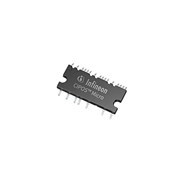
The Infineon IM241L6S1BAUMA1 is a CIPOS™ Micro intelligent power module (IPM) integrating a three-phase inverter stage in a single 23-PowerSMD package with gull-wing leads. Rated for a 600 V collector-emitter breakdown and a maximum power dissipation of 15 W, it covers the 50 W to 200 W motor-drive class typical of refrigerator compressors, washing-machine drum drives, and HVAC fan motors.
The 600 V breakdown sets the DC bus voltage ceiling — it comfortably handles a 310 V DC bus from a 230 V AC rectified line with margin for switching overshoot. The 15 W power limit is the total dissipation across all six IGBTs; derate it by the junction-to-ambient thermal resistance of the 23-SOP package, which typically needs a small heatsink or PCB copper area for continuous operation above 5 W to 8 W. The integrated NTC thermistor (Yes) lets the controller read the module's internal temperature directly through a simple resistor divider — no external thermistor, no extra routing. This is a BOM simplification that also improves thermal response time because the sensor sits on the same substrate as the IGBTs. At 2 A per phase, that is about 3.2 W conduction loss in the low-side IGBTs alone — within the 15 W budget but leaving limited headroom for switching losses at higher PWM frequencies. For a 10 kHz PWM fan drive it is fine; for a 20 kHz ultrasonic cleaner drive, budget a heatsink.
The 23-PowerSMD Module with gull-wing leads is a surface-mount power package designed for reflow soldering. The gull-wing form gives visible solder joints for inspection, unlike a QFN or BGA. The 23-SOP footprint is compact — roughly 12 mm × 12 mm — but the power dissipation means the PCB layout must include a thermal pad with via stitching to inner copper planes. Without that, the junction temperature will exceed 150°C at the 15 W limit. Mounting type is Surface Mount, so no through-hole heatsink tab. The datasheet's recommended land pattern should be followed exactly; the gull-wing leads are fine-pitch and a misaligned stencil can cause solder bridging between adjacent power pins.