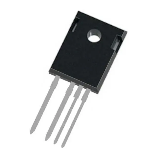
Infineon Technologies IKZA50N65SS5XKSA1 — Logic ICs

Infineon IKZA50N65SS5XKSA1 IGBT, TrenchStop 5, 650 V, 80 A

MPNIKZA50N65SS5XKSA1
End of Life

Infineon TrenchStop™ 5 IGBT, IKZA50N65SS5XKSA1, 650 V collector-emitter breakdown, 80 A continuous collector current, 1.7 V Vce(on) at 15 V / 50 A, 110 nC gate charge, PG-TO247-4-3 package, through-hole mount, -40°C to 175°C junction temperature.

$12.2Ref. price · indicative, final on quote
PackagingTO-247-4
StockContact for availability
MOQ1 pcs
  • 100% new & originalTraceable channels only — no refurbs, no pulls, no remarked parts.
  • Date & lot codes on quoteStated per line before you commit; label photos on request.
  • MSL-compliant ESD packingMoisture-sealed bags with indicator cards; reels photo-verified.
  • PayPal buyer protectionPay by T/T, PayPal or Payoneer — card payments covered end to end.

Specifications

IKZA50N65SS5XKSA1 Technical Specifications
ParameterValue
SeriesTrenchStop™ 5
IGBT typeTrench Field Stop
Input typeStandard
Mounting typeThrough Hole
Voltage - collector emitter breakdown650 V
Current - collector (Ic)80 A
Current - collector pulsed200 A
Power - max274 W
Operating temperature-40°C ~ 175°C (TJ)
PackageTube
Gate charge110 nC
CaseTO-247-4
Test condition400V, 50A, 9Ohm, 15V
Switching energy230µJ (on), 520µJ (off)
Td (on/off) @ 25°C19ns/140ns
Vce(on) (Max) @ vge, ic1.7V @ 15V, 50A

Product details

TrenchStop 5 IGBT for 650 V power stages

The Infineon IKZA50N65SS5XKSA1 is a 650 V, 80 A Trench Field Stop IGBT from the TrenchStop™ 5 series, housed in a PG-TO247-4-3 through-hole package. It targets hard-switching applications such as motor drives, UPS inverters, solar string inverters, and welding converters where low conduction loss and controlled switching behaviour are required. The 650 V breakdown voltage provides margin for 400 V DC-link rails common in three-phase industrial drives.

Conduction and switching loss profile

At the test condition of 400 V bus, 50 A collector current, 9 Ω gate resistor, and 15 V gate drive, the device delivers a typical Vce(on) of 1.7 V. That on-state voltage sets the conduction loss at rated current — at 50 A, expect roughly 85 W conduction loss per device before switching losses are added. The switching energy totals 750 µJ per cycle (230 µJ turn-on, 520 µJ turn-off) under the same test condition. For a 20 kHz switching frequency, that adds about 15 W of switching loss, which together with conduction loss determines the heatsink requirement. The 110 nC gate charge is moderate for this current class; a standard IGBT driver with 2 A to 4 A peak source/sink capability will handle the turn-on and turn-off edges cleanly.

Thermal and ruggedness envelope

Maximum power dissipation is 274 W. The 200 A pulsed collector current rating (Icm) gives short-circuit withstand margin for desaturation protection circuits. The TO-247-4 package separates the Kelvin emitter from the power emitter, which reduces gate-loop inductance and improves switching behaviour compared to a standard TO-247-3 — the fourth pin is the Kelvin emitter connection, not a second collector. This matters for layout: the gate-driver return should route to the Kelvin pin, not the power emitter tab.

Lifecycle and supply position

This part is qualified for ongoing production and new design-ins.

Frequently asked questions

What is the Vce(on) of IKZA50N65SS5XKSA1?

The typical Vce(on) is 1.7 V at 15 V gate drive and 50 A collector current, measured under the test condition of 400 V bus and 9 Ω gate resistor.

What is the gate charge of IKZA50N65SS5XKSA1?

The gate charge is 110 nC. This is a moderate figure for an 80 A rated device, allowing use with standard IGBT gate drivers in the 2 A to 4 A peak current range.

Where can I buy IKZA50N65SS5XKSA1 and how do I get a price?

Submit an RFQ for current availability and pricing; both are confirmed at quote time.