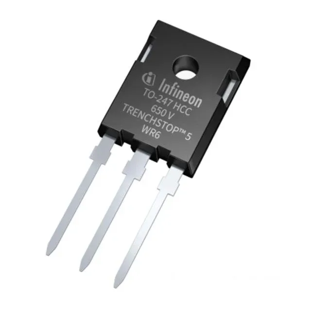
650 V, 75 A trench IGBT for inverter and power stages
The Infineon IKWH40N65WR6XKSA1 is a 650 V, 75 A trench-gate IGBT from the TrenchStop™ 5 WR6 series, housed in a TO-247-3 through-hole package (PG-TO247-3-32). It targets hard-switching applications such as motor drives, UPS inverters, and solar string inverters where conduction and switching losses must balance against thermal budget.
Conduction and switching loss at the operating point
At the test condition of 400 V rail, 40 A collector current, 27 Ω gate resistor, and 15 V gate drive, the device delivers a typical Vce(on) of 1.85 V — the conduction loss floor at that point. Switching energy measures 1.09 mJ during turn-on and 570 µJ during turn-off, with a turn-on delay of 37 ns and turn-off delay of 353 ns at 25 °C junction. The 117 nC total gate charge sets the drive current required from the gate driver IC. At a 20 kHz switching frequency, the average gate drive current is roughly 2.3 mA; at 100 kHz it rises to 11.7 mA, still within the capability of most isolated gate drivers, but the gate resistor value must be chosen to keep the turn-on di/dt within the diode reverse recovery capability.
Thermal and current capability
Maximum power dissipation is 175 W. The continuous collector current rating of 75 A and pulsed current capability of 120 A give headroom for overload and start-up transients. The 650 V collector-emitter breakdown voltage provides margin on a 400 V DC bus, but derating for high-temperature leakage and switching overvoltage spikes should follow the safe operating area in the datasheet. The TO-247-3 package with a large copper tab allows heatsink mounting; the thermal resistance junction-to-case determines the heatsink size for the target junction temperature at full load.