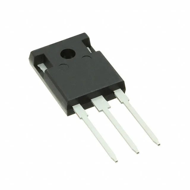
Infineon Technologies IKW40T120FKSA1

Infineon IKW40T120FKSA1 IGBT, 1200 V 75 A TO-247-3

MPNIKW40T120FKSA1
End of Life

Infineon TrenchStop IGBT, IKW40T120FKSA1, NPT Trench Field Stop, 1200 V Vces, 75 A Ic, 2.3 V Vce(on) at 15 V / 40 A, 270 W, TO-247-3 through-hole, -40 to 150 °C.

$9.07Ref. price · indicative, final on quote
PackagingTO-247-3
StockContact for availability
MOQ1 pcs
  • 100% new & originalTraceable channels only — no refurbs, no pulls, no remarked parts.
  • Date & lot codes on quoteStated per line before you commit; label photos on request.
  • MSL-compliant ESD packingMoisture-sealed bags with indicator cards; reels photo-verified.
  • PayPal buyer protectionPay by T/T, PayPal or Payoneer — card payments covered end to end.

Specifications

IKW40T120FKSA1 Technical Specifications
ParameterValue
SeriesTrenchStop®
IGBT typeNPT, Trench Field Stop
Input typeStandard
Mounting typeThrough Hole
Voltage - collector emitter breakdown1200 V
Current - collector (Ic)75 A
Current - collector pulsed105 A
Power - max270 W
Operating temperature-40°C ~ 150°C (TJ)
PackageTube
Gate charge203 nC
CaseTO-247-3
Test condition600V, 40A, 15Ohm, 15V
Switching energy6.5mJ
Td (on/off) @ 25°C48ns/480ns
Vce(on) (Max) @ vge, ic2.3V @ 15V, 40A
Reverse recovery time240 ns

Product details

1200 V / 75 A TrenchStop IGBT in TO-247-3

The Infineon IKW40T120FKSA1 is a 1200 V, 75 A NPT Trench Field Stop IGBT from the TrenchStop series, housed in a PG-TO247-3-1 through-hole package. It targets hard-switching applications such as motor drives, UPS inverters, and welding converters where the 1200 V collector-emitter breakdown voltage provides margin for 400 VAC to 690 VAC bus rails, and the 75 A continuous collector current supports 10–30 kW output stages with appropriate heatsinking.

Conduction and switching losses at the operating point

At the test condition of 600 V, 40 A, 15 Ω gate resistor, and 15 V gate drive, the typical Vce(on) is 2.3 V — this on-state voltage sets the conduction loss floor. For a 40 A rms phase current, the conduction loss per device is roughly 92 W, which must be sunk by the heatsink. The total switching energy per cycle is 6.5 mJ; at a 10 kHz switching frequency that adds 65 W of dynamic loss, pushing the junction toward the 270 W power-max ceiling. The 240 ns reverse recovery time on the co-packaged diode is fast enough for most IGBT switching speeds but should be verified against the diode's own recovery losses in the target topology.

Temperature range and thermal design

The operating junction temperature range is -40 to 150 °C. The 150 °C maximum junction is typical for TrenchStop IGBTs and allows a reasonable thermal headroom above the 125 °C limit of older planar devices. The turn-on delay is 48 ns and turn-off delay is 480 ns at 25 °C; the turn-off tail is the dominant switching loss contributor at higher junction temperatures. Gate charge is 203 nC — a standard 15 V gate driver with 2 A peak source/sink can charge and discharge the gate in under 100 ns, keeping switching edges clean.

Frequently asked questions

What is the Vce(sat) and max current for IKW40T120?

The typical Vce(on) is 2.3 V at 15 V gate drive and 40 A collector current. The maximum continuous collector current is 75 A, and the pulsed collector current rating is 105 A.