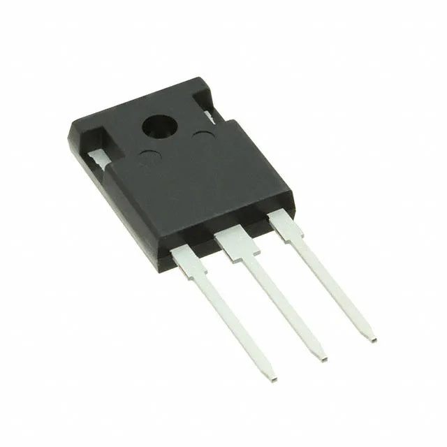
Infineon Technologies IKW25N120CS7XKSA1 — Logic ICs

IKW25N120CS7XKSA1 IGBT, 1200 V, 55 A, TO-247-3, AEC-Q101

MPNIKW25N120CS7XKSA1
End of Life

Infineon Automotive TrenchStop IGBT, IKW25N120CS7XKSA1, Trench Field Stop, 1200 V Vces, 55 A Ic, 250 W, Vce(on) 2 V @ 15 V / 25 A, TO-247-3, -40 to 175 °C, AEC-Q101.

$6.01Ref. price · indicative, final on quote
PackagingTO-247-3
StockContact for availability
MOQ1 pcs
  • 100% new & originalTraceable channels only — no refurbs, no pulls, no remarked parts.
  • Date & lot codes on quoteStated per line before you commit; label photos on request.
  • MSL-compliant ESD packingMoisture-sealed bags with indicator cards; reels photo-verified.
  • PayPal buyer protectionPay by T/T, PayPal or Payoneer — card payments covered end to end.

Specifications

IKW25N120CS7XKSA1 Technical Specifications
ParameterValue
SeriesAutomotive, AEC-Q101, TrenchStop™
IGBT typeTrench Field Stop
Input typeStandard
Mounting typeThrough Hole
Voltage - collector emitter breakdown1200 V
Current - collector (Ic)55 A
Current - collector pulsed75 A
Power - max250 W
Operating temperature-40°C ~ 175°C (TJ)
PackageTube
Gate charge150 nC
CaseTO-247-3
Test condition600V, 25A, 6Ohm, 15V
Switching energy1.2mJ (on), 1.1mJ (off)
Td (on/off) @ 25°C21ns/160ns
Vce(on) (Max) @ vge, ic2V @ 15V, 25A
Reverse recovery time150 ns

Product details

1200 V trench field-stop IGBT for automotive traction and industrial inverters

The Infineon IKW25N120CS7XKSA1 is a 1200 V, 55 A Trench Field Stop IGBT from the Automotive TrenchStop series, housed in a through-hole TO-247-3 package. It's built for the high-side switch in three-phase inverter legs, on-board charger PFC stages, and DC-DC converters where the DC bus sits at 800 V or below. The Trench Field Stop structure keeps the saturation voltage at 2 V typical at 25 A and 15 V gate drive, which means conduction losses stay manageable even at full load. The 150 nC gate charge figure tells the gate-drive designer what peak current the driver needs to hit the target switching speed — plan for a driver that can source and sink at least 2 A to keep the turn-on and turn-off edges clean.

Switching performance under the hood

Tested at 600 V, 25 A with a 6 Ω gate resistor and 15 V gate drive, this part switches on in 21 ns and off in 160 ns, with 1.2 mJ turn-on energy and 1.1 mJ turn-off energy. The 150 ns reverse recovery time of the co-packaged diode matters when you're hard-switching into an inductive load — it sets the dead-time floor and the recovery loss contribution. For a 16 kHz switching frequency inverter, those switching losses add up to about 37 W at the test condition, so the 250 W power dissipation rating gives enough thermal headroom if the heatsink is sized properly.

Automotive qualification and production status

The ROHS3 compliance means no exemption-based headaches for EU-market builds. For a production BOM that needs a second-source hedge, the TrenchStop family includes several 1200 V TO-247 parts with similar pinouts — the closest parametric match would share the same Vce(sat) and switching energy profile, but the exact cross-reference depends on your gate drive voltage and switching frequency. The active lifecycle means no LTB risk for the next few years, but if you're planning a five-year production run, it's worth asking Infineon for the PCN notification enrollment on this series.

Package and mounting considerations

The PG-TO247-3 package is the standard three-lead through-hole format with the centre pin as collector. The tab is electrically live (collector potential), so the heatsink needs an insulating pad or a thermal interface material rated for 1200 V isolation. The 250 W dissipation assumes the case is held at 25 °C — in practice, expect to derate to about 100 W with a forced-air heatsink at 85 °C ambient.

Frequently asked questions

What are the exact specifications of IKW25N120CS7XKSA1?

The IKW25N120CS7XKSA1 is a 1200 V, 55 A continuous collector current IGBT with a pulsed current rating of 75 A. It uses Trench Field Stop technology, has a saturation voltage of 2 V at 15 V gate drive and 25 A, a gate charge of 150 nC, and switching energies of 1.2 mJ (on) and 1.1 mJ (off) tested at 600 V, 25 A with a 6 Ω gate resistor. The package is TO-247-3, and it operates from -40 °C to 175 °C junction temperature.

Is IKW25N120CS7XKSA1 qualified for automotive applications?

Yes, it belongs to the Automotive series and is AEC-Q101 qualified, making it suitable for automotive-grade designs including traction inverters, on-board chargers, and DC-DC converters in hybrid and electric vehicles.

What are the switching characteristics of IKW25N120CS7XKSA1 (td(on), td(off), switching energy)?

At 25 °C with a 600 V bus, 25 A collector current, 6 Ω gate resistor, and 15 V gate drive, the turn-on delay is 21 ns, turn-off delay is 160 ns, turn-on switching energy is 1.2 mJ, and turn-off switching energy is 1.1 mJ.

What is the gate charge of IKW25N120CS7XKSA1?

The total gate charge is 150 nC, measured at the test condition of 600 V and 25 A.