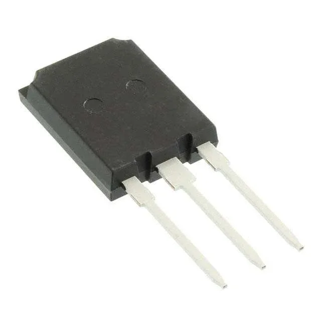
Infineon Technologies IKQ120N60TXKSA1

Infineon IKQ120N60TXKSA1 IGBT, 600 V, 160 A, TrenchStop™

MPNIKQ120N60TXKSA1
End of Life

Infineon TrenchStop™ IGBT, IKQ120N60TXKSA1, 600 V, 160 A, Trench Field Stop, 2 V Vce(on) at 15 V, 120 A, 833 W, TO-247-3, Through Hole, -40°C to 175°C.

$13.45Ref. price · indicative, final on quote
PackagingTO-247-3
StockContact for availability
MOQ1 pcs
  • 100% new & originalTraceable channels only — no refurbs, no pulls, no remarked parts.
  • Date & lot codes on quoteStated per line before you commit; label photos on request.
  • MSL-compliant ESD packingMoisture-sealed bags with indicator cards; reels photo-verified.
  • PayPal buyer protectionPay by T/T, PayPal or Payoneer — card payments covered end to end.

Specifications

IKQ120N60TXKSA1 Technical Specifications
ParameterValue
SeriesTrenchStop™
IGBT typeTrench Field Stop
Input typeStandard
Mounting typeThrough Hole
Voltage - collector emitter breakdown600 V
Current - collector (Ic)160 A
Current - collector pulsed480 A
Power - max833 W
Operating temperature-40°C ~ 175°C (TJ)
PackageTube
Gate charge703 nC
CaseTO-247-3
Test condition400V, 120A, 3Ohm, 15V
Switching energy6.2mJ (on), 5.9mJ (off)
Td (on/off) @ 25°C50ns/565ns
Vce(on) (Max) @ vge, ic2V @ 15V, 120A
Reverse recovery time241 ns

Product details

600 V, 160 A — the conduction-loss ceiling

The IKQ120N60TXKSA1 is a 600 V, 160 A Trench Field Stop IGBT from Infineon's TrenchStop™ series, housed in a TO-247-3 through-hole package. It targets the sweet spot for 400 V DC-link motor drives, UPS inverters, and solar string inverters where the bus voltage sits around 400 V and the peak collector current reaches 160 A continuous, 480 A pulsed. The 2 V typical Vce(on) at 120 A collector current and 15 V gate drive sets the conduction-loss floor. At full load the 2 V drop times 120 A gives 240 W of conduction loss alone — the 833 W maximum power dissipation gives headroom for switching losses, but the heatsink must be sized for the sum.

Switching losses and gate drive budget

Switching energy is 6.2 mJ turn-on and 5.9 mJ turn-off under the test condition of 400 V, 120 A, 3 Ohm gate resistor, 15 V gate drive. At a 10 kHz switching frequency, that adds roughly 121 W of switching loss — combined with conduction loss, the die temperature stays within the -40°C to 175°C junction range only with adequate thermal management. The 703 nC total gate charge means the gate driver must source and sink that charge each cycle. A driver with 2 A peak output can charge the gate in about 350 ns; a weaker driver stretches the switching edges and increases turn-on loss. Turn-on delay is 50 ns, turn-off delay 565 ns at 25°C. The asymmetric delay — fast turn-on, slower turn-off — is typical of Trench Field Stop designs and must be accounted for in dead-time settings to avoid shoot-through.

Active production, ROHS3 compliant

The part ships in the PG-TO247-3-46 package variant, a standard TO-247-3 footprint. The through-hole mounting suits high-power stages where the leads carry the current and the tab bolts to a heatsink.

Frequently asked questions

Is IKQ120N60TXKSA1 ROHS compliant?

Yes, it is ROHS3 compliant.

How does IKQ120N60TXKSA1 compare to IKW120N60T?

Both are 600 V, 120 A class TrenchStop IGBTs in TO-247 packages. The IKQ variant typically offers lower Vce(on) and faster switching at the cost of slightly higher gate charge — the exact parametric differences should be verified against the respective datasheets for your operating point.