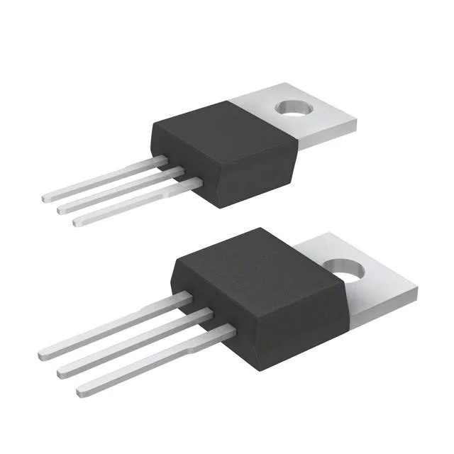
Infineon Technologies IKP40N65F5XKSA1

IKP40N65F5XKSA1 IGBT 650V 74A TO-220-3 TrenchStop®

MPNIKP40N65F5XKSA1
End of Life

Infineon TrenchStop® IGBT, IKP40N65F5XKSA1, 650 V, 74 A, 255 W, 95 nC, Through Hole, PG-TO220-3.

$3.88Ref. price · indicative, final on quote
PackagingTO-220-3
StockContact for availability
MOQ1 pcs
  • 100% new & originalTraceable channels only — no refurbs, no pulls, no remarked parts.
  • Date & lot codes on quoteStated per line before you commit; label photos on request.
  • MSL-compliant ESD packingMoisture-sealed bags with indicator cards; reels photo-verified.
  • PayPal buyer protectionPay by T/T, PayPal or Payoneer — card payments covered end to end.

Specifications

IKP40N65F5XKSA1 Technical Specifications
ParameterValue
SeriesTrenchStop®
Input typeStandard
Mounting typeThrough Hole
Voltage - collector emitter breakdown650 V
Current - collector (Ic)74 A
Current - collector pulsed120 A
Power - max255 W
Operating temperature-40°C ~ 175°C (TJ)
PackageTube
Gate charge95 nC
CaseTO-220-3
Test condition400V, 20A, 15Ohm, 15V
Switching energy360µJ (on), 100µJ (off)
Td (on/off) @ 25°C19ns/160ns
Vce(on) (Max) @ vge, ic2.1V @ 15V, 40A
Reverse recovery time60 ns

Product details

650 V, 74 A TrenchStop® IGBT in TO-220-3

The Infineon IKP40N65F5XKSA1 is a 650 V, 74 A TrenchStop® IGBT in a through-hole PG-TO220-3 package. It is designed for hard-switching applications such as motor drives, uninterruptible power supplies, and industrial inverters where low conduction and switching losses are needed. The 95 nC gate charge keeps the gate-drive power budget modest, and the 175 °C maximum junction temperature allows operation in high-ambient enclosures or engine compartments.

Switching performance and thermal headroom

Rated at 74 A continuous collector current with a 120 A pulsed capability, this IGBT handles the inrush and overload events common in motor-start and capacitor-charging circuits. The switching energy of 360 µJ (on) and 100 µJ (off), measured at 400 V, 20 A, and 15 Ω gate resistance, gives a realistic loss figure for hard-switching topologies. The 60 ns reverse recovery time of the co-packaged diode reduces turn-on losses in the complementary switch. The 2.1 V saturation voltage at 15 V gate drive and 40 A collector current defines the on-state loss at typical operating points. With a 255 W power dissipation limit and 175 °C junction rating, the designer has headroom to push switching frequency or ambient temperature as long as the thermal path to the heatsink is adequate.

Lifecycle and BOM fit

Listed as Active with ROHS3 compliance, the IKP40N65F5XKSA1 carries no last-time-buy risk for current production. The standard TO-220-3 footprint and through-hole mounting simplify assembly and field replacement.

Frequently asked questions

What is the IKP40N65F5XKSA1 datasheet?

Design engineers need full electrical characteristics and package information to validate fit in their circuit.

Is IKP40N65F5XKSA1 in stock?

Sourcing buyers need immediate availability to avoid production delays.

What is the price of IKP40N65F5XKSA1?

Buyers compare costs across distributors to optimize BOM spending.

Where to buy IKP40N65F5XKSA1?

Directs purchasers to authorized distributors ensuring genuine parts.

What are the equivalents of IKP40N65F5XKSA1?

Engineers and buyers need alternative parts for sourcing flexibility or second-source approval.

What is the pinout of IKP40N65F5XKSA1?

Helps design engineers and technicians verify board layout and avoid connection errors.