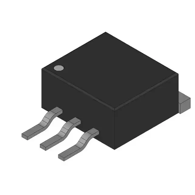
600 V, 30 A TrenchStop IGBT in a TO-252 surface-mount package
It is a standard-input, N-channel trench device rated for 250 W maximum power dissipation.
Conduction and switching losses at the test point
At the test condition of 400 V, 15 A, 15 Ohm gate resistance, and 15 V gate drive, the IKD15N60RBTMA1 exhibits a Vce(on) of 2.1 V typical and a total switching energy of 900 µJ. The turn-on delay is 16 ns and turn-off delay is 183 ns at 25°C. The 90 nC total gate charge means a gate driver must supply roughly 90 nC × fsw of average current; at a 20 kHz switching frequency that is about 1.8 mA, well within the capability of most standard gate-driver ICs. The reverse recovery time of the co-packaged diode is 110 ns, which contributes to the turn-on loss in hard-switched topologies.
Package and mounting — PG-TO252-3-11
The PG-TO252-3-11 (DPak) package has two leads plus a tab that is the collector connection. The 0.50 mm lead pitch is standard for this footprint.