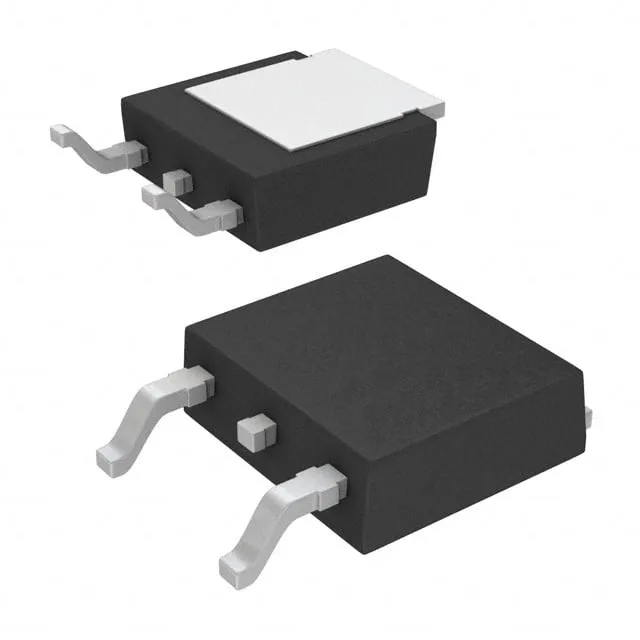
600 V TrenchStop IGBT in a surface-mount DPAK
It is designed for medium-frequency switching applications such as motor drives, power factor correction (PFC) circuits, and general-purpose inverters where conduction and switching losses must be balanced. The Trench Field Stop structure delivers a low saturation voltage of 2.3 V typical at 15 V gate drive and 6 A collector current, combined with a tight switching energy profile of 170 µJ turn-on and 80 µJ turn-off under the standard test condition of 400 V, 6 A, 49 Ω gate resistance, and 15 V gate drive.
Switching losses and gate drive requirements
With a gate charge of 31 nC, the IKD06N60RC2ATMA1 presents a moderate load to the gate driver, suitable for both dedicated IGBT drivers and bootstrap half-bridge configurations. The turn-on delay is 6 ns and turn-off delay is 129 ns at 25°C, meaning the switching transition times are dominated by the external gate resistor and the Miller plateau. The 170 µJ turn-on and 80 µJ turn-off energies at 400 V / 6 A give a reasonable starting point for estimating dissipation at a given switching frequency — expect to derate for higher junction temperatures, as the switching losses typically increase above 125°C.
The PG-TO252-3 (DPAK) package has a tab that is electrically common with the collector. The part is ROHS3 compliant.