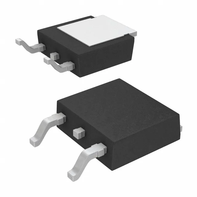
Infineon Technologies IKD04N60RATMA1

Infineon IKD04N60RATMA1 TrenchStop IGBT, 600 V 8 A, TO-252-3

MPNIKD04N60RATMA1
End of Life

Infineon TrenchStop IGBT, IKD04N60RATMA1, 600 V, 8 A, 75 W, Trench Field Stop, 27 nC gate charge, 90/150 µJ switching energy, TO-252-3 (DPak) surface-mount package, -40°C to 175°C junction temperature.

$1.01Ref. price · indicative, final on quote
PackagingTO-252-3, DPak (2 Leads + Tab), SC-63
StockContact for availability
MOQ1 pcs
  • 100% new & originalTraceable channels only — no refurbs, no pulls, no remarked parts.
  • Date & lot codes on quoteStated per line before you commit; label photos on request.
  • MSL-compliant ESD packingMoisture-sealed bags with indicator cards; reels photo-verified.
  • PayPal buyer protectionPay by T/T, PayPal or Payoneer — card payments covered end to end.

Specifications

IKD04N60RATMA1 Technical Specifications
ParameterValue
SeriesTrenchStop™
IGBT typeTrench Field Stop
Input typeStandard
Mounting typeSurface Mount
Voltage - collector emitter breakdown600 V
Current - collector (Ic)8 A
Current - collector pulsed12 A
Power - max75 W
Operating temperature-40°C ~ 175°C (TJ)
PackageTape & Reel (TR); Cut Tape (CT)
Gate charge27 nC
CaseTO-252-3, DPak (2 Leads + Tab), SC-63
Test condition400V, 4A, 43Ohm, 15V
Switching energy90µJ (on), 150µJ (off)
Td (on/off) @ 25°C14ns/146ns
Vce(on) (Max) @ vge, ic2.1V @ 15V, 4A
Reverse recovery time43 ns

Product details

600 V, 8 A TrenchStop IGBT in a surface-mount DPak

It is designed for medium-power switched-mode applications where a low on-state voltage drop and controlled switching losses are required. With a maximum power dissipation of 75 W and a junction temperature range from -40°C to 175°C, this part suits environments with wide thermal excursions, such as motor drives, power inverters, and battery chargers in industrial or automotive under-hood settings.

Switching performance and gate drive requirements

The IKD04N60RATMA1 specifies a total gate charge of 27 nC, which sets the drive current needed from the gate driver for the target switching frequency. For example, switching at 50 kHz would require an average gate drive current of roughly 1.35 mA, well within the capability of most standard gate-driver ICs. Switching energy is characterised at 400 V, 4 A with a 43 Ω gate resistor: 90 µJ during turn-on and 150 µJ during turn-off. These values let a designer estimate the switching-loss contribution to the total thermal budget for a given operating frequency. Turn-on delay is 14 ns and turn-off delay is 146 ns at 25°C, giving a fast enough response for hard-switched topologies up to several tens of kilohertz.

Conduction losses and thermal design

The collector-emitter saturation voltage Vce(on) is specified at 2.1 V maximum at 15 V gate drive and 4 A collector current. This on-state voltage directly sets the conduction loss: at 4 A, the conduction loss per IGBT is roughly 8.4 W, which must be dissipated through the DPak's exposed pad to the PCB copper. The part is rated for a pulsed collector current of 12 A, providing headroom for short-duration overloads or inrush events typical in motor-start and capacitor-charging applications.

Package and assembly considerations

The PG-TO252-3 (DPak) surface-mount package has two leads plus a tab that serves as the collector connection and primary thermal path.

Lifecycle and compliance status

It is ROHS3 compliant, meeting the latest restriction-of-hazardous-substances requirements for lead-free soldering processes.

Frequently asked questions

Is IKD04N60RATMA1 RoHS compliant?

Yes, the IKD04N60RATMA1 is ROHS3 compliant, suitable for lead-free soldering processes.