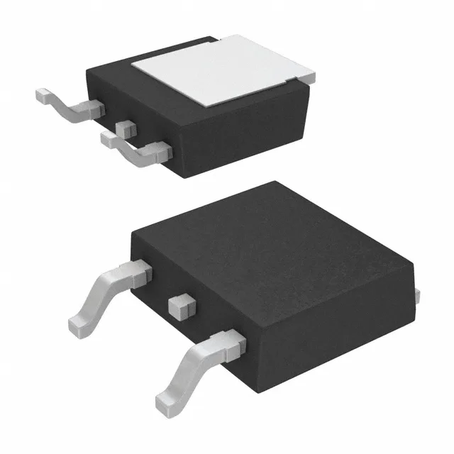
Infineon Technologies IKD03N60RFATMA1

IKD03N60RFATMA1 TrenchStop™ IGBT, 600 V 6.5 A, TO-252-3

MPNIKD03N60RFATMA1
End of Life

Infineon TrenchStop™ IGBT, IKD03N60RFATMA1, 600 V, 6.5 A, 53.6 W, 17.1 nC gate charge, Trench Field Stop, Surface Mount, TO-252-3 (DPak), -40°C to 175°C.

$0.93Ref. price · indicative, final on quote
PackagingTO-252-3, DPak (2 Leads + Tab), SC-63
StockContact for availability
MOQ1 pcs
  • 100% new & originalTraceable channels only — no refurbs, no pulls, no remarked parts.
  • Date & lot codes on quoteStated per line before you commit; label photos on request.
  • MSL-compliant ESD packingMoisture-sealed bags with indicator cards; reels photo-verified.
  • PayPal buyer protectionPay by T/T, PayPal or Payoneer — card payments covered end to end.

Specifications

IKD03N60RFATMA1 Technical Specifications
ParameterValue
SeriesTrenchStop™
IGBT typeTrench Field Stop
Input typeStandard
Mounting typeSurface Mount
Voltage - collector emitter breakdown600 V
Current - collector (Ic)6.5 A
Current - collector pulsed7.5 A
Power - max53.6 W
Operating temperature-40°C ~ 175°C (TJ)
PackageTape & Reel (TR); Cut Tape (CT)
Gate charge17.1 nC
CaseTO-252-3, DPak (2 Leads + Tab), SC-63
Test condition400V, 2.5A, 68Ohm, 15V
Switching energy50µJ (on), 40µJ (off)
Td (on/off) @ 25°C10ns/128ns
Vce(on) (Max) @ vge, ic2.5V @ 15V, 2.5A
Reverse recovery time31 ns

Product details

600 V / 6.5 A TrenchStop™ in a TO-252-3 — what the scorch mark tells you

The Infineon IKD03N60RFATMA1 is a TrenchStop™ IGBT with a 600 V collector-emitter breakdown voltage and 6.5 A continuous collector current, housed in a surface-mount TO-252-3 (DPak) package. It uses a Trench Field Stop structure with standard input logic, so it gates directly from a typical MCU or gate-driver output without a level shifter. The 17.1 nC gate charge keeps the drive current low — a 100 mA driver can switch it at 50 kHz without breaking a sweat.

Vce(sat) max is 2.5 V at 15 V gate drive and 2.5 A collector current — that's the conduction loss floor at the test condition. In a 2.5 A load, expect about 6.25 W conduction loss before switching losses. The switching energy numbers (50 µJ turn-on, 40 µJ turn-off at 400 V, 2.5 A, 68 Ω gate resistor, 15 V gate drive) tell you the total switching loss at 50 kHz is roughly 4.5 W — well within the 53.6 W power max rating, but the TO-252-3's thermal pad needs a good copper pour to keep junction temperature below 175 °C.

Package and board-fit reality

The PG-TO252-3 (DPak) footprint is standard — three leads plus the tab, 2.3 mm pitch. The tab is the collector, so the PCB copper pour under it doubles as the heatsink. Surface-mount reflow profile: typical 260 °C peak, but the 175 °C junction rating means the die itself can take the heat. No through-hole tab to solder — the whole joint is reflow, so inspect the tab wetting angle under the part after reflow; a cold joint under the tab is the failure signature you'll find on a dead PFC stage.

Frequently asked questions

What is the Vce(sat) of IKD03N60RFATMA1?

Maximum Vce(sat) is 2.5 V at 15 V gate drive and 2.5 A collector current. This is the conduction loss spec at the test condition.

Is IKD03N60RFATMA1 RoHS compliant?

Yes, it is listed as ROHS3 compliant.