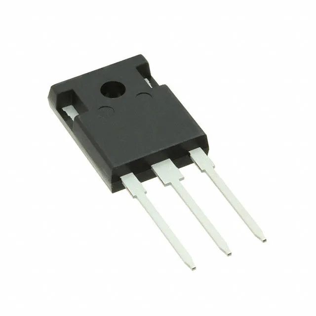
Infineon Technologies IHW30N110R5XKSA1

IHW30N110R5XKSA1 IGBT, 60 A, 330 W, TO-247-3

MPNIHW30N110R5XKSA1
End of Life

Infineon TRENCHSTOP IGBT, IHW30N110R5XKSA1, 60 A continuous collector, 330 W max power, 1.85 V Vce(sat) at 15 V / 30 A, 240 nC gate charge, TO-247-3 through-hole, -40 to 175 °C junction.

$4.28Ref. price · indicative, final on quote
PackagingTO-247-3
StockContact for availability
MOQ1 pcs
  • 100% new & originalTraceable channels only — no refurbs, no pulls, no remarked parts.
  • Date & lot codes on quoteStated per line before you commit; label photos on request.
  • MSL-compliant ESD packingMoisture-sealed bags with indicator cards; reels photo-verified.
  • PayPal buyer protectionPay by T/T, PayPal or Payoneer — card payments covered end to end.

Specifications

IHW30N110R5XKSA1 Technical Specifications
ParameterValue
Input typeStandard
Mounting typeThrough Hole
Current - collector (Ic)60 A
Current - collector pulsed90 A
Power - max330 W
Operating temperature-40°C ~ 175°C (TJ)
PackageTube
Gate charge240 nC
CaseTO-247-3
Td (on/off) @ 25°C-/350ns
Vce(on) (Max) @ vge, ic1.85V @ 15V, 30A

Product details

Trench IGBT for hard-switching up to 60 A

The Infineon IHW30N110R5XKSA1 is a 60 A trench-gate IGBT in a TO-247-3 through-hole package, rated for 330 W maximum power dissipation. The 1.85 V typical saturation voltage at 15 V gate drive and 30 A collector current sets the conduction loss floor — a key number when sizing the heatsink for a motor-drive or inverter stage.

Gate charge and switching speed

Total gate charge is 240 nC. That figure drives the gate-driver peak-current requirement: a 240 nC gate at a 20 kHz switching frequency draws an average 4.8 mA from the driver, but the turn-on edge needs a short pulse of several amps to charge the input capacitance within the desired dead-time window. The datasheet lists a 350 ns turn-off delay at 25 °C — the turn-on delay is not specified here, so bench verification of the full switching waveform is recommended for timing-critical designs.

Junction temperature and operating environment

The 175 °C Tj max is the absolute ceiling — the designer must derate the continuous collector current above 100 °C per the datasheet's thermal curve to stay inside the SOA.

Sourcing and lifecycle status

ROHS3 compliant.

Frequently asked questions

What is the Vce(sat) of the IHW30N110R5XKSA1?

The typical Vce(sat) is 1.85 V at a gate voltage of 15 V and a collector current of 30 A. This is the conduction-loss spec used for heatsink and efficiency calculations in hard-switched topologies.