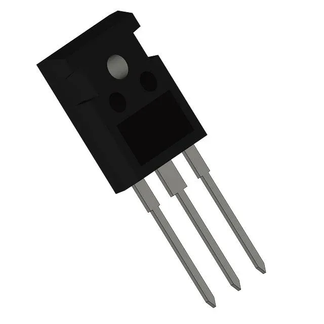
Infineon Technologies IHW20N135R3

Infineon IHW20N135R3 Reverse Conducting IGBT, 1350 V, 40 A

MPNIHW20N135R3
End of Life

Infineon IHW20N135R3 reverse conducting IGBT, Trench Field Stop, 1350 V, 40 A, 1.8 V Vce(sat) @ 15 V / 20 A, 195 nC gate charge, 310 W, TO-247-3, -40 to 175 °C.

$2.11Ref. price · indicative, final on quote
PackagingTO-247-3
StockContact for availability
MOQ1 pcs
  • 100% new & originalTraceable channels only — no refurbs, no pulls, no remarked parts.
  • Date & lot codes on quoteStated per line before you commit; label photos on request.
  • MSL-compliant ESD packingMoisture-sealed bags with indicator cards; reels photo-verified.
  • PayPal buyer protectionPay by T/T, PayPal or Payoneer — card payments covered end to end.

Specifications

IHW20N135R3 Technical Specifications
ParameterValue
IGBT typeTrench Field Stop
Input typeStandard
Mounting typeThrough Hole
Voltage - collector emitter breakdown1350 V
Current - collector (Ic)40 A
Current - collector pulsed60 A
Power - max310 W
Operating temperature-40°C ~ 175°C (TJ)
PackageBulk
Gate charge195 nC
CaseTO-247-3
Test condition600V, 20A, 15Ohm, 15V
Switching energy-, 1.3mJ (off)
Td (on/off) @ 25°C-/335ns
Vce(on) (Max) @ vge, ic1.8V @ 15V, 20A

Product details

Reverse-conducting IGBT with monolithic diode

The Infineon IHW20N135R3 is a reverse-conducting IGBT (RC-IGBT) that integrates the anti-parallel freewheeling diode monolithically into the Trench Field Stop die. This eliminates the external diode and its package parasitics, reducing loop inductance and board area in resonant converters, induction heating, and soft-switching power stages. The part is rated for 1350 V collector-emitter breakdown and 40 A continuous collector current, with a maximum junction temperature of 175 °C. The TO-247-3 package (PG-TO247-3-41) is a through-hole package standard for high-power through-hole designs.

1350 V breakdown and 175 °C junction — what they mean for the design

Gate charge is 195 nC. Turn-off delay is 335 ns.

Switching energy and test conditions

Turn-off energy is specified at 1.3 mJ under test conditions of 600 V bus, 20 A collector current, 15 Ω gate resistor, and 15 V gate drive. That 1.3 mJ is the dominant loss term in hard-switched topologies; designers targeting switching frequencies above 20 kHz should derate the output current or plan for a larger heatsink to keep junction temperature within the 175 °C limit.

Active lifecycle, ROHS3, and sourcing posture

The IHW20N135R3 carries an Active product status with no announced end-of-life. It is ROHS3 compliant.

Frequently asked questions

What is a reverse conducting IGBT?

A reverse-conducting IGBT (RC-IGBT) integrates the anti-parallel freewheeling diode into the same silicon die as the IGBT. This eliminates the external diode, reduces package count, and lowers loop inductance — particularly beneficial in resonant and soft-switching topologies where the diode conducts during the resonant cycle.

What are the specifications of IHW20N135R3?

Key ratings: 1350 V collector-emitter breakdown, 40 A continuous collector current, 60 A pulsed, 1.8 V Vce(sat) at 15 V / 20 A, 195 nC gate charge, 1.3 mJ turn-off energy at 600 V / 20 A, 310 W max power dissipation, -40 to 175 °C junction temperature, TO-247-3 package.

How does IHW20N135R3 compare to a standard IGBT with external diode?

The IHW20N135R3 monolithically integrates the freewheeling diode, saving the cost and board area of a separate diode package and eliminating the interconnect inductance between the IGBT and diode. This reduces switching loop inductance and can improve efficiency in resonant topologies. The trade-off is that the monolithic diode's characteristics are fixed — you cannot independently select a faster or softer-recovery diode for a given application.