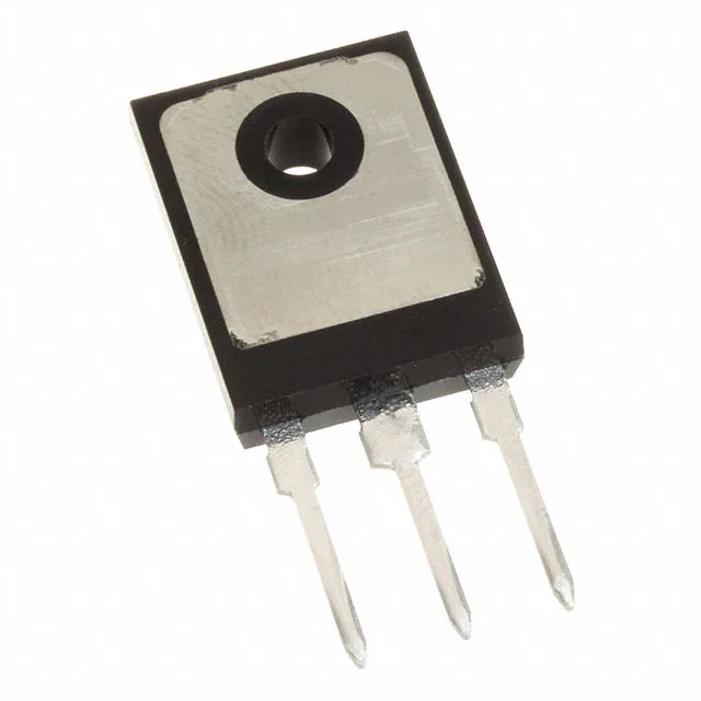
Infineon Technologies IGW30N65L5XKSA1

Infineon IGW30N65L5XKSA1 IGBT, 650 V 30 A TrenchStop 5

MPNIGW30N65L5XKSA1
End of Life

Infineon TrenchStop™ 5 IGBT, IGW30N65L5XKSA1, 650 V, 85 A continuous, 30 A test condition, 168 nC gate charge, 227 W max power, TO-247-3 through-hole, -40°C to 175°C junction.

$3.95Ref. price · indicative, final on quote
PackagingTO-247-3
StockContact for availability
MOQ1 pcs
  • 100% new & originalTraceable channels only — no refurbs, no pulls, no remarked parts.
  • Date & lot codes on quoteStated per line before you commit; label photos on request.
  • MSL-compliant ESD packingMoisture-sealed bags with indicator cards; reels photo-verified.
  • PayPal buyer protectionPay by T/T, PayPal or Payoneer — card payments covered end to end.

Specifications

IGW30N65L5XKSA1 Technical Specifications
ParameterValue
SeriesTrenchStop™ 5
Input typeStandard
Mounting typeThrough Hole
Voltage - collector emitter breakdown650 V
Current - collector (Ic)85 A
Current - collector pulsed120 A
Power - max227 W
Operating temperature-40°C ~ 175°C (TJ)
PackageTube
Gate charge168 nC
CaseTO-247-3
Test condition400V, 30A, 10Ohm, 15V
Switching energy470µJ (on), 1.35mJ (off)
Td (on/off) @ 25°C33ns/308ns
Vce(on) (Max) @ vge, ic1.35V @ 15V, 30A

Product details

Switching losses and thermal reality

At the test condition of 400 V, 30 A, 10 Ω, 15 V, the turn-on energy is 470 µJ and turn-off is 1.35 mJ. The 1.35 V saturation voltage at 15 V, 30 A is competitive.

Package and mounting

The PG-TO247-3 package is a standard through-hole power tab. Torque the mounting screw to the usual TO-247 spec with a thermal interface material rated for the 175°C junction temperature.

Frequently asked questions

Can I use IGW30N65L5XKSA1 in a motor drive?

Yes, the 650 V breakdown voltage gives headroom on a 400 V DC bus, and the 30 A continuous rating with 85 A peak capability suits 2-5 kW motor drives. The 1.35 mJ turn-off energy at 30 A means the heatsink must handle switching losses at typical 8-16 kHz PWM frequencies.

What is the recommended gate resistor for IGW30N65L5XKSA1?

The test condition uses a 10 Ω gate resistor with a 15 V gate drive. That's a good starting point for 20-40 kHz hard switching. For slower speeds or to reduce EMI, increase the resistor; for faster switching, decrease it, but watch for ringing on the gate waveform.