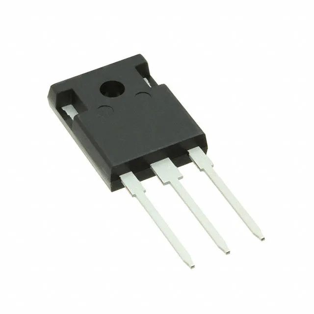
Infineon Technologies IGW25T120FKSA1

Infineon IGW25T120FKSA1 IGBT, 1200 V 50 A TO-247-3

MPNIGW25T120FKSA1
End of Life

Infineon TrenchStop® IGBT, IGW25T120FKSA1, NPT Trench Field Stop, 1200 V Vces, 50 A Ic, 2.2 V Vce(on) @ 15 V / 25 A, 155 nC Qg, 190 W, TO-247-3, Through Hole, -40°C to 150°C.

$5.93Ref. price · indicative, final on quote
PackagingTO-247-3
StockContact for availability
MOQ1 pcs
  • 100% new & originalTraceable channels only — no refurbs, no pulls, no remarked parts.
  • Date & lot codes on quoteStated per line before you commit; label photos on request.
  • MSL-compliant ESD packingMoisture-sealed bags with indicator cards; reels photo-verified.
  • PayPal buyer protectionPay by T/T, PayPal or Payoneer — card payments covered end to end.

Specifications

IGW25T120FKSA1 Technical Specifications
ParameterValue
SeriesTrenchStop®
IGBT typeNPT, Trench Field Stop
Input typeStandard
Mounting typeThrough Hole
Voltage - collector emitter breakdown1200 V
Current - collector (Ic)50 A
Current - collector pulsed75 A
Power - max190 W
Operating temperature-40°C ~ 150°C (TJ)
PackageTube
Gate charge155 nC
CaseTO-247-3
Test condition600V, 25A, 22Ohm, 15V
Switching energy4.2mJ
Td (on/off) @ 25°C50ns/560ns
Vce(on) (Max) @ vge, ic2.2V @ 15V, 25A

Product details

1200 V / 50 A TrenchStop IGBT in TO-247-3

The Infineon IGW25T120FKSA1 is a 1200 V, 50 A NPT Trench Field Stop IGBT from the TrenchStop series, housed in a through-hole TO-247-3 package. It is designed for hard-switching power conversion in industrial drives, UPS systems, and welding inverters where 1200 V bus voltage isolation and 150°C junction capability are required.

Conduction and switching losses at the operating point

At the test condition of 600 V bus, 25 A collector current, 22 Ω gate resistor, and 15 V gate drive, the IGW25T120FKSA1 delivers a Vce(on) of 2.2 V typical and a total switching energy of 4.2 mJ. The 155 nC gate charge sets the drive current requirement — a typical gate driver with 2 A peak source/sink capability will switch this device in the 50 ns turn-on / 560 ns turn-off window at 25°C. The 190 W maximum power dissipation in the TO-247 package means the thermal interface to the heatsink is the limiting factor for continuous current — expect to derate from the 50 A Ic rating in real-world enclosures above 100°C case temperature.

Package, mounting, and temperature grade

The PG-TO247-3-1 supplier package is a standard TO-247 with three leads and an isolated mounting hole. The through-hole leads require a 0.040-inch (1.0 mm) drilled hole per lead in the PCB, with adequate creepage distance — at 1200 V working voltage, 6.4 mm minimum clearance per IEC 60950 is typical between collector tab and any grounded heatsink. Rated for continuous junction operation from -40°C to 150°C, this IGBT suits outdoor telecom rectifiers, solar inverter DC-AC stages, and motor drive output stages where the ambient may cycle below freezing.

Lifecycle and compliance status

ROHS3 compliant, with no lead in the solder plating or mould compound. No official second-source or pin-compatible replacement is listed; the TrenchStop series is Infineon's own platform, so cross-shopping a competitor's TO-247 IGBT requires verifying the gate threshold voltage window and the switching energy trade-off at the same test condition.

Frequently asked questions

What is the gate charge of the IGW25T120FKSA1?

The total gate charge (Qg) is 155 nC, measured at the test condition of 600 V DC bus and 25 A collector current with a 15 V gate drive. This value determines the average gate drive current needed at the target switching frequency — for example, at 20 kHz switching, the average drive current is 3.1 mA per device.

What is the closest pin-compatible alternative to the IGW25T120FKSA1?

No official pin-compatible second source or replacement is listed in the component record. The TO-247-3 footprint is standard across the industry, so any 1200 V, 50 A class IGBT in TO-247 from another manufacturer will share the same pinout — but verify the gate threshold voltage range and the switching energy at your specific operating point before substituting.