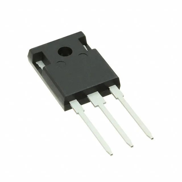
Infineon Technologies IGW25N120H3FKSA1

IGW25N120H3FKSA1 IGBT, 1200 V, 50 A, TrenchStop, TO-247-3

MPNIGW25N120H3FKSA1
End of Life

Infineon TrenchStop IGBT, IGW25N120H3FKSA1, 1200 V, 50 A, 326 W, TO-247-3, Through Hole, -40°C to 175°C.

$6.08Ref. price · indicative, final on quote
PackagingTO-247-3
StockContact for availability
MOQ1 pcs
  • 100% new & originalTraceable channels only — no refurbs, no pulls, no remarked parts.
  • Date & lot codes on quoteStated per line before you commit; label photos on request.
  • MSL-compliant ESD packingMoisture-sealed bags with indicator cards; reels photo-verified.
  • PayPal buyer protectionPay by T/T, PayPal or Payoneer — card payments covered end to end.

Specifications

IGW25N120H3FKSA1 Technical Specifications
ParameterValue
SeriesTrenchStop®
IGBT typeTrench Field Stop
Input typeStandard
Mounting typeThrough Hole
Voltage - collector emitter breakdown1200 V
Current - collector (Ic)50 A
Current - collector pulsed100 A
Power - max326 W
Operating temperature-40°C ~ 175°C (TJ)
PackageTube
Gate charge115 nC
CaseTO-247-3
Test condition600V, 25A, 23Ohm, 15V
Switching energy2.65mJ
Td (on/off) @ 25°C27ns/277ns
Vce(on) (Max) @ vge, ic2.4V @ 15V, 25A

Product details

1200 V, 50 A TrenchStop IGBT in TO-247-3

The Infineon IGW25N120H3FKSA1 is a Trench Field Stop IGBT rated for 1200 V collector-emitter breakdown and 50 A continuous collector current, housed in a through-hole TO-247-3 package. It is part of the TrenchStop series, designed for high-efficiency switching in motor drives, inverters, and power supplies where conduction and switching losses both matter.

Conduction and switching — what the numbers mean

Vce(on) is 2.4 V typical at 15 V gate drive and 25 A collector current — that is the conduction loss floor at the nominal operating point. Total gate charge is 115 nC, which sets the drive current required to hit a target switching frequency. Switching energy is 2.65 mJ under the test condition of 600 V bus, 25 A, 23 Ohm gate resistor, and 15 V gate drive. That figure includes both turn-on and turn-off losses — use it to estimate per-cycle dissipation at the intended switching frequency. Turn-on delay is 27 ns and turn-off delay is 277 ns at 25°C junction. The asymmetric delay means dead-time in a half-bridge leg should be set to accommodate the longer turn-off, typically 300 ns or more.

Junction temperature and package

The 326 W power dissipation rating assumes the case is held at 25°C — real-world derating depends on the heatsink and thermal interface. The TO-247-3 package (PG-TO247-3-1) is a standard through-hole power package with a large copper tab for heatsinking.

ROHS3 compliant.

Frequently asked questions

Is IGW25N120H3FKSA1 obsolete or end of life?

No — the product status is listed as active.

Can I use IGW25N120H3FKSA1 in a motor drive application?

Yes. The 1200 V breakdown, 50 A continuous rating, and 175°C junction temperature make it suitable for motor-drive inverter stages, particularly where the DC bus is 400 V to 600 V and the load current is in the 20–30 A range.