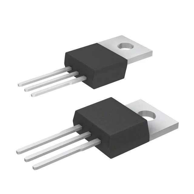
The IGP20N65F5XKSA1: The 650 V collector-emitter breakdown voltage gives headroom on a 400 V DC bus — enough margin for the inductive spikes that appear during hard-switched turn-off. The 42 A continuous collector current rating covers motor-drive and inverter stages up to about 2 kW output, depending on heatsinking and switching frequency. Pulsed current capability reaches 60 A, which handles inrush and short-circuit events within the IGBT's SOA. The 125 W maximum power dissipation sets the thermal budget: at 20 A and 2.1 V Vce(on), conduction losses alone eat 42 W, leaving about 83 W for switching losses before the junction hits 175 °C.
Switching losses — 160 µJ on, 60 µJ off
Under the test condition of 400 V, 10 A, 32 Ω gate resistor, and 15 V gate drive, the part dissipates 160 µJ during turn-on and 60 µJ during turn-off. At a 20 kHz switching frequency, that adds about 4.4 W of switching loss — a number to plug into the thermal model alongside the conduction loss. The 48 nC total gate charge means a standard IGBT driver with 1 A peak output can switch the gate in roughly 48 ns, keeping Miller-plateau duration short and reducing cross-conduction risk.
TO-220-3 — mounting and thermal interface
The PG-TO220-3 package is a through-hole part with a metal tab for heatsink mounting. The tab is electrically common with the collector, so an insulating pad and thermal grease are needed if the heatsink is grounded.