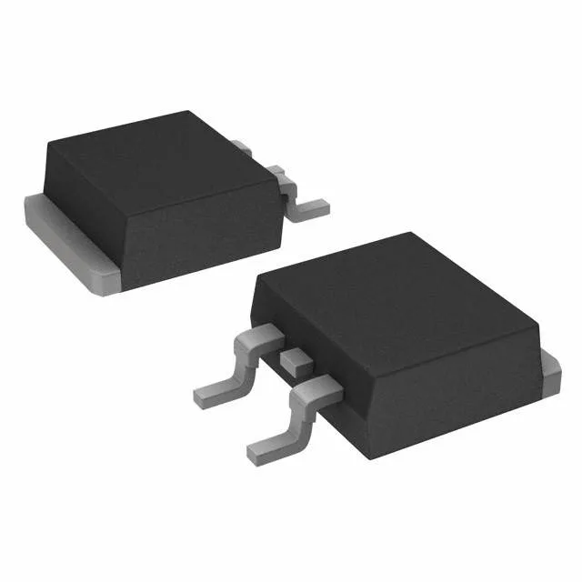
600 V, 100 A trench IGBT for motor drives and inverters
It is designed for medium-power switching applications such as motor drives, uninterruptible power supplies, and welding converters where conduction losses and switching speed both matter.
On-state voltage and switching energy
At a gate voltage of 15 V and collector current of 50 A, the typical Vce(on) is 2 V. The total switching energy at 400 V, 50 A, 7 Ohm gate resistor, and 15 V gate drive is 2.6 mJ. Turn-on delay is 26 ns and turn-off delay 299 ns at 25°C — the 299 ns turn-off dominates the switching loss at frequencies above 10 kHz.
Gate drive and thermal design
Gate charge is 310 nC total. A gate driver must source this charge within the desired switching period — at 20 kHz, the average gate-drive current is about 6.2 mA, but peak current is higher and depends on the gate resistor. The 7 Ohm test-condition gate resistor is a starting point; adjust for EMI vs. switching loss trade-off. This extra headroom helps in overload conditions or high-ambient environments like enclosed motor drives.
It is ROHS3 compliant.