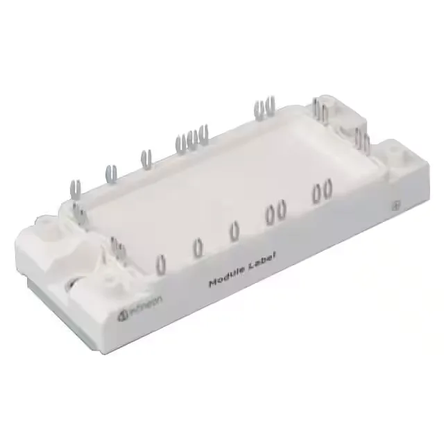
Infineon Technologies FS50R07N2E4_B11

Infineon FS50R07N2E4_B11 IGBT Module

MPNFS50R07N2E4_B11
End of Life

Infineon FS50R07N2E4_B11 EconoPACK™ 2 IGBT module, Trench Field Stop, Three Phase Inverter, 650 V, 70 A, 190 W, NTC thermistor, chassis mount, -40°C to 150°C.

$49.97Ref. price · indicative, final on quote
PackagingModule
StockContact for availability
MOQ1 pcs
  • 100% new & originalTraceable channels only — no refurbs, no pulls, no remarked parts.
  • Date & lot codes on quoteStated per line before you commit; label photos on request.
  • MSL-compliant ESD packingMoisture-sealed bags with indicator cards; reels photo-verified.
  • PayPal buyer protectionPay by T/T, PayPal or Payoneer — card payments covered end to end.

Specifications

FS50R07N2E4_B11 Technical Specifications
ParameterValue
SeriesEconoPACK™ 2
IGBT typeTrench Field Stop
Mounting typeChassis Mount
Voltage - collector emitter breakdown650 V
Current - collector (Ic)70 A
Current - collector cutoff1 mA
Power - max190 W
Operating temperature-40°C ~ 150°C (TJ)
InputStandard
PackageBulk
ConfigurationThree Phase Inverter
NTC thermistorYes
CaseModule
Vce(on) (Max) @ vge, ic1.95V @ 15V, 50A
Input capacitance (Cies) @ vce3.1 nF @ 25 V

Product details

650 V, 70 A three-phase inverter module — the EconoPACK™ 2 floor

The Infineon FS50R07N2E4_B11 is a 650 V, 70 A IGBT module in the EconoPACK™ 2 series, configured as a three-phase inverter with six Trench Field Stop IGBTs and anti-parallel diodes in a single module. The module is rated for a maximum power dissipation of 190 W and includes an integrated NTC thermistor for direct junction-temperature monitoring — no external sensor needed. Junction temperature range covers -40°C to 150°C, suiting industrial motor drives, servo drives, and grid-tied inverters where the module is chassis-mounted and the baseplate is cooled via a heatsink or cold plate.

At the rated operating point of 50 A collector current with a 15 V gate drive, the typical Vce(on) is 1.95 V — this sets the conduction loss floor at 97.5 W per IGBT at that current, which drives the thermal resistance budget to the heatsink. The input capacitance (Cies) is 3.1 nF at 25 V collector-emitter, which gives the gate-driver designer a load for sizing the peak gate current and the drive power — a standard 15 V gate driver with a few amps peak can handle the switching without excessive cross-conduction. Collector-emitter breakdown is rated at 650 V, so the module can safely operate on a 400 VDC bus (typical for three-phase 230 VAC input drives) with margin for switching overshoot.

Active production, ROHS3, and NTC integration

The NTC thermistor is wired to auxiliary pins on the module — the resistance-vs-temperature curve is published in the datasheet and lets the control board read junction temperature without a separate sensor.

Frequently asked questions

What is the maximum operating frequency of FS50R07N2E4_B11?

The evidence does not specify a maximum switching frequency. The practical limit depends on the gate-driver strength, heatsink thermal impedance, and acceptable switching losses — the 3.1 nF input capacitance and 1.95 V Vce(on) suggest a typical hard-switched inverter design in the 4–16 kHz range for motor-drive applications.

Is FS50R07N2E4_B11 RoHS compliant?

Yes, the FS50R07N2E4_B11 is listed as ROHS3 compliant.