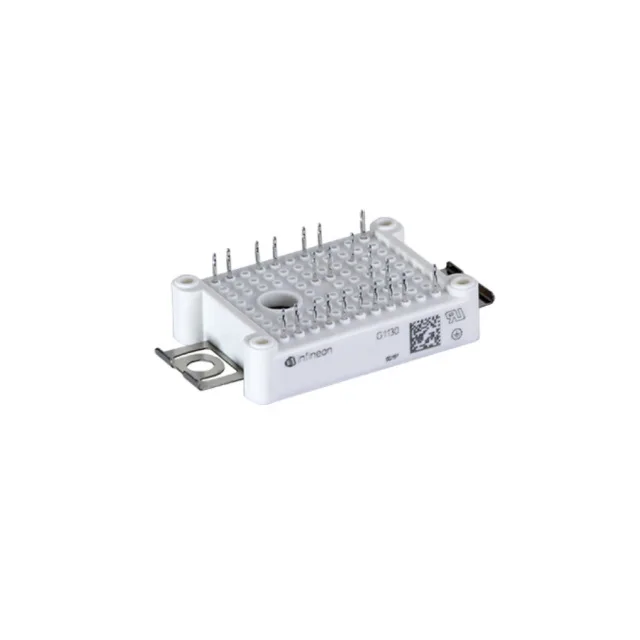
650 V / 40 A dual IGBT module for inverter and motor-drive stages
It contains two independent IGBTs with a common collector configuration, designed for chassis-mount installation in industrial inverter, motor drive, and power conversion equipment.
What the 650 V breakdown and 40 A collector rating mean for your power stage
The 650 V collector-emitter breakdown voltage gives headroom for a 400 V DC bus with margin for switching transients and bus pumping during regenerative braking. The 40 A continuous collector current per switch handles typical 5–10 kW motor drives when derated for junction temperature. The 1.55 V typical Vce(on) at 15 V gate drive and 25 A means conduction losses stay manageable at partial load — the saturation voltage is specified at a test current well below the 40 A max, so expect higher Vce(on) near the full rating. The 2.8 nF input capacitance at 25 V Vce sets the gate drive energy per switching cycle; a standard 15 V gate driver with a few ohms of external gate resistance will drive it cleanly.
NTC thermistor: built-in thermal monitoring without extra wiring
The integrated NTC thermistor reports the module baseplate temperature directly, letting the controller fold back switching frequency or current limit before the 150°C maximum junction is reached. This saves a thermistor mounting step and keeps the thermal path short — the NTC sits on the ceramic substrate, not on a distant heatsink tab.
For new designs, this module can be specified without an obsolescence watch.