Dual-core M4/M0 architecture and memory budget
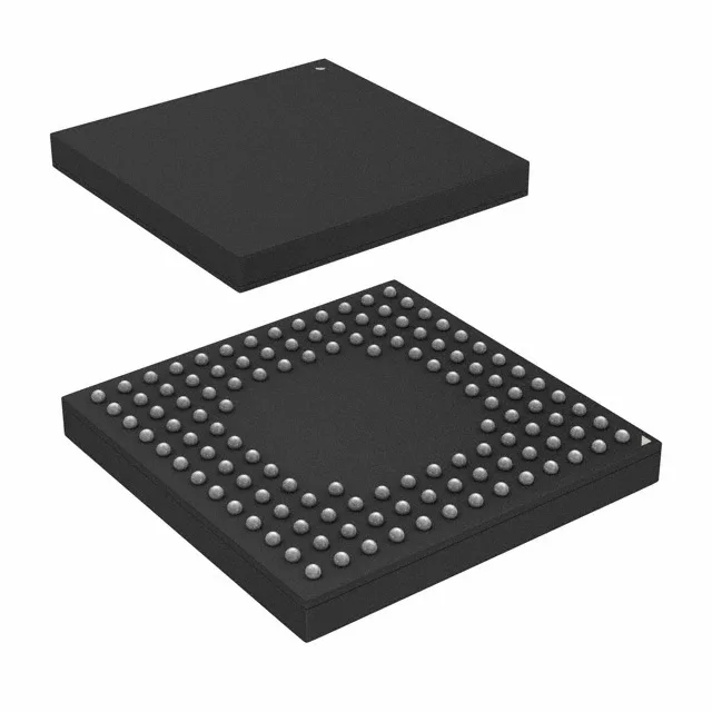
The CY8C6247BZI-D34 is a PSoC® 6 series MCU built around a 32-bit dual-core ARM Cortex-M4 running up to 150 MHz and a Cortex-M0 core at 100 MHz. The M4 handles application code and DSP; the M0 offloads real-time I/O, security, and power-management tasks, letting the main core sleep longer in battery-powered designs. On-chip memory totals 1 MB flash (1M x 8), 288 KB SRAM (288K x 8), and 32 KB EEPROM (32K x 8) — enough to run a full RTOS, TCP/IP stack, and application logic without external memory. The 104 I/O pins in the 124-VFBGA (9x9 mm) package give ample room for parallel buses and sensor interfaces.
Supply range, temperature grade, and analog peripherals
The analog subsystem includes an 8-channel 12-bit SAR ADC (1x12b DAC) for sensor conditioning, plus CapSense for capacitive touch interfaces. Brown-out detect, POR, and watchdog timers provide the supervision needed for unattended field operation.
Connectivity and peripheral set
Connectivity covers USB, QSPI, LINbus, I²C, SPI, UART/USART, and I²S — enough to bridge to Wi-Fi/BLE modules, external flash, and industrial fieldbuses. DMA channels offload data movement from the CPU. The PWM timers and LIN support make this MCU a candidate for motor-control nodes and automotive-adjacent HMI panels, though it lacks an AEC-Q automotive grade — the industrial temp range suits factory-floor and commercial vehicle interiors.
The closest peer in the PSoC 6 family is the CY8C6137BZI-F54, a single-core M4 at 150 MHz in the same 124-VFBGA package. The CY8C6247BZI-D34 adds the M0 core for power-domain separation — a meaningful difference if your firmware splits real-time and application tasks. Both share the same pinout and peripheral set, so a board designed for one can accept the other with a firmware change.