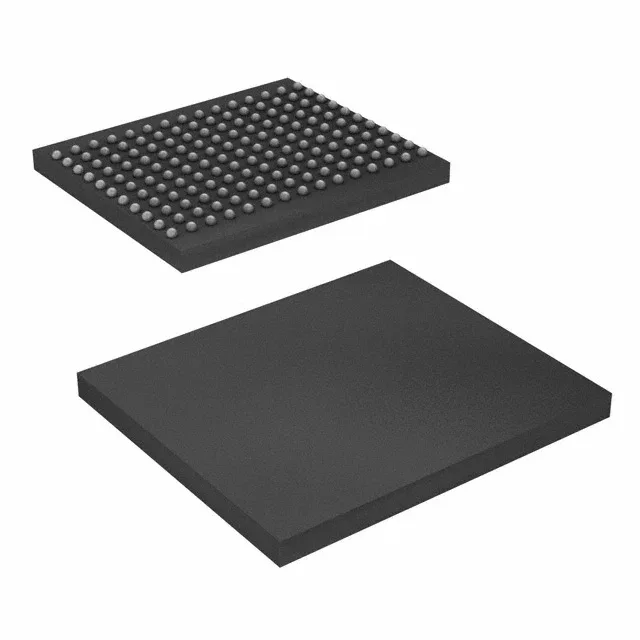
The 500 MHz clock frequency gives a burst data rate that suits high-bandwidth, low-latency buffer applications in networking equipment, test instrumentation, and baseband processing where the QDR II+ interface eliminates the read-write bus-turnaround dead cycles of traditional SRAM. It is packaged in a 165-ball FBGA (13x15 mm) for surface-mount assembly.
500 MHz clock — the timing constraint
The 500 MHz clock frequency sets the internal pipeline and I/O timing. At this speed, signal-integrity on the parallel bus is critical: trace-length matching, controlled impedance, and proper termination on the QDR II+ data and address lines are non-negotiable. The 1.7V to 1.9V supply range is tighter than a standard 1.8V rail — your power supply must stay within that window under load transients, or the part may lose data integrity.