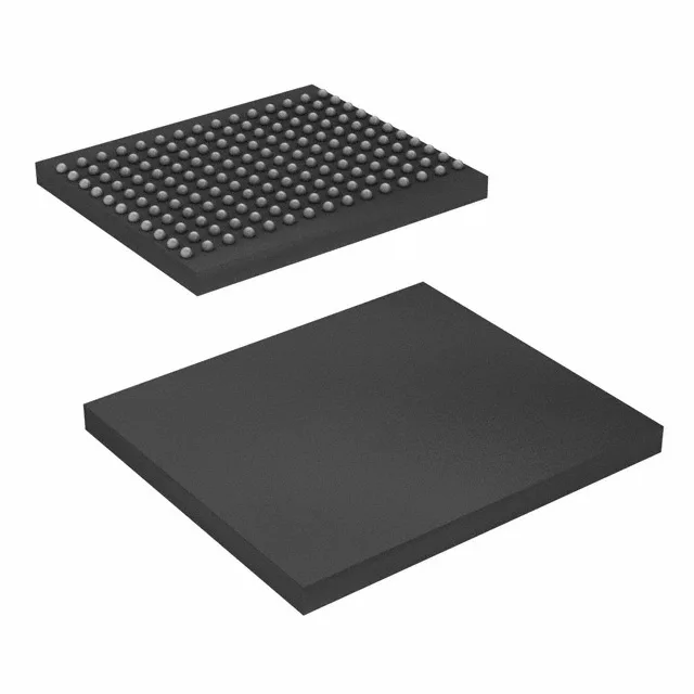
The CY7C25652KV18-400BZXC: Its 400 MHz clock rate delivers a peak data rate that keeps high-bandwidth buffers fed in networking, telecom line cards, and test equipment where read-write turnaround latency is critical. The QDR II+ bus eliminates dead cycles between read and write operations, so back-to-back throughput stays close to the theoretical maximum — a key advantage over standard synchronous SRAMs that insert idle turns.
The 165-FBGA (13x15 mm) package is a fine-pitch BGA. On the layout side, route the 36-bit data bus plus address and control signals through the inner balls; keep decoupling caps within 2 mm of the supply balls to maintain signal integrity at 400 MHz.
If your board already carries a 1.8 V supply for other logic, budget the peak current draw from the datasheet's active current spec — the 400 MHz operation pulls a non-trivial transient load. A dedicated LDO or a low-noise buck converter with 1% accuracy keeps the rail inside the window. The 1.7 V lower edge is tight: a 1.8 V rail with 5% tolerance dips to 1.71 V, which is still legal, but any additional drop from IR loss on the PCB trace pushes it under. Use a separate power plane or a wide trace from the regulator output.
It is not rated for outdoor telecom cabinets, factory floors, or automotive under-hood applications. If your design needs to live in an unventilated enclosure that can hit 85°C, look at the industrial-temperature variant in this family (the suffix changes from C to I).
For production orders, the standard lead time through distribution applies — quoted at the time of your RFQ.