It clocks at 450 MHz over a parallel interface, which translates to a peak read/write throughput that keeps packet buffers and look-up tables fed in high-end networking and telecom equipment. The 36-bit word width leaves room for parity or ECC on a 32-bit data bus — a common choice in NPU and FPGA-attached memory. Supply runs at 1.7V to 1.9V, so the board's core rail needs tight regulation; the 1.7V floor is the number to check during brownout or cold-crank analysis.
QDR II+ — why the bus-turnaround matters
Standard synchronous SRAMs insert dead cycles when switching from read to write (or write to read). QDR II+ eliminates that turnaround penalty by dedicating separate data ports for read and write, allowing back-to-back transactions at full clock rate. For a 450 MHz part, that means no wasted cycles on a congested memory bus — directly relevant for line-rate packet processing where every clock counts. The 2M x 36 organization also means the device can handle a 32-bit data word plus a 4-bit sideband (tag, parity, or ECC) in a single access, reducing the total device count on the board.
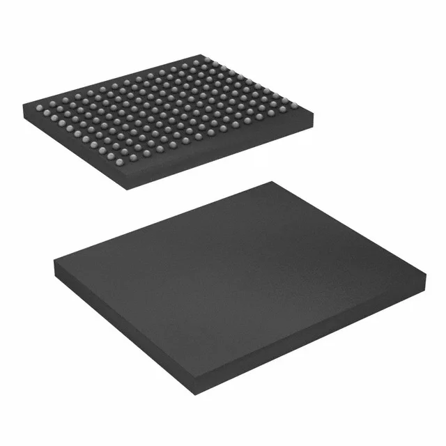
The device comes in a 165-ball FBGA measuring 13x15 mm (supplier device package 165-FBGA). It is a surface-mount BGA; the ball pitch and layout dictate the fan-out via pattern and the number of PCB layers needed to escape the inner balls. Decoupling should follow the manufacturer's recommendation — typically a 0.1 µF cap per supply ball pair, placed as close to the balls as the via pattern allows. The Tray shipping medium is standard for this package; if your pick-and-place feeder expects tape, verify the tray-to-tape conversion with your assembler before committing the line.