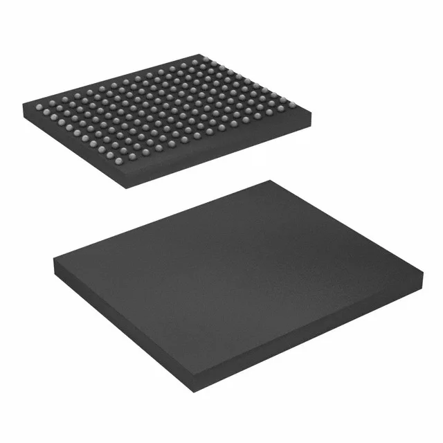
QDR II SRAM — what this chip does on the board
At a 300 MHz clock, each port delivers 600 MHz effective data rate, which is what line-card and switch-fabric designs need for back-to-back read-write throughput without stalling the pipeline. Organised as 2M x 9 (two 1M x 9 ports), it uses a parallel interface and runs from a 1.7V to 1.9V core supply. That puts it squarely in indoor telecom racks, test equipment, and enterprise networking gear — not in outdoor or under-hood environments where the ambient exceeds 70°C.
Obsolete — the sourcing reality for this BGA memory
A pin-compatible QDR II SRAM (e.g. a different speed bin or a later density) would require a board respin or at minimum a timing re-characterisation; there is no drop-in replacement with the same footprint and timing that Cypress certifies as a direct swap.
At 300 MHz, the QDR II interface delivers a 3.33 ns clock period. The read and write data buses are source-synchronous with echo clocks, so the timing budget is tight: the board trace length matching between the SRAM and the controller (FPGA or ASIC) needs to stay within roughly ±0.5 inches on a typical FR4 stack-up to avoid setup/hold violations. If you are replacing a failed unit on an existing board, the original layout already accounts for this; a substitute with a different package or speed grade will shift the flight times and likely break the margin.
165-FBGA — rework and handling notes
The 165-ball FBGA (13x15 mm, 1 mm ball pitch) is a standard BGA footprint for this density class. Reballing is possible with a stencil and the right solder sphere diameter, but the fine pitch means the hot-air profile must be tight — too much top-side heat and the package cracks; too little and the centre balls don't collapse. The tape-and-reel shipping format suggests this was originally intended for high-volume pick-and-place, but for replacement quantities you will typically receive the parts in cut tape or trays from the surplus channel.