It operates at a 250 MHz clock frequency with a parallel memory interface, requiring a 1.7V to 1.9V core supply.
250 MHz clock and 2M x 9 organization — bus timing and buffer sizing
The 250 MHz clock rate defines the maximum random access cycle time. At this speed, the QDR II architecture eliminates the bus-turnaround dead cycles typical of traditional SRAMs, sustaining full-rate reads and writes on alternating edges. The 2M x 9 organization (18 Mbit total) provides a 9-bit-wide data path, which suits designs that need a narrow, high-speed buffer — for example, a 9-bit-wide FIFO or a tag RAM in a cache controller. The 1.7V to 1.9V supply range is tight; the board's power rail must be regulated to within that window, and decoupling at the BGA balls should follow the layout guidelines for QDR II devices to maintain signal integrity at 250 MHz.
165-FBGA package — layout considerations
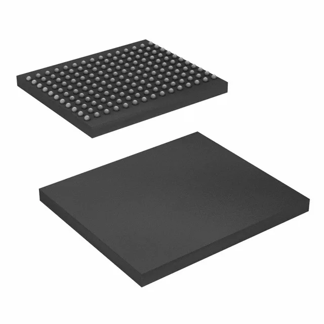
The 165-ball FBGA (13x15 mm) is a fine-pitch BGA. Surface-mount assembly requires controlled solder-paste volume and X-ray inspection for voiding and shorts.