QDR II+ SRAM for high-throughput buffer applications
The 400 MHz clock rate delivers a peak data rate of 800 MHz DDR per port, making this part suited for high-bandwidth buffer applications in networking switches, routers, and telecom line cards where sustained back-to-back throughput is required.
At 400 MHz the QDR II+ interface clocks data on both edges, so the effective data rate per port is 800 MT/s. For a design that chains back-to-back reads and writes — typical in packet buffer memory — the separate read and write ports mean no idle cycles for bus turnaround. The timing closure budget at this speed demands tight PCB layout: matched trace lengths, controlled impedance on the data and address lines, and decoupling within 5 mm of each supply pin.
It fits indoor equipment with controlled climate — central-office telecom, data-center switches, test equipment — but not outdoor or under-hood environments. No AEC-Q qualification is listed, so automotive or extended-industrial use would require a different temperature-grade variant.
Package and PCB integration
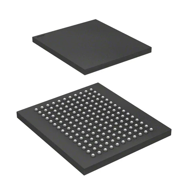
The 165-FBGA (15x17 mm) package uses a 1.0 mm ball pitch typical of high-density BGA SRAM. Surface-mount assembly requires a solder-paste stencil with aperture sizing matched to the ball diameter; the 165-ball array routes the 18-bit data bus and address lines on inner layers. The Tray shipping medium is standard for BGA devices — no tape-and-reel option is listed in the spec, so pick-and-place feeders need tray-to-tape conversion or a tray handler.
For BOM planning this removes the obsolescence risk for new designs.