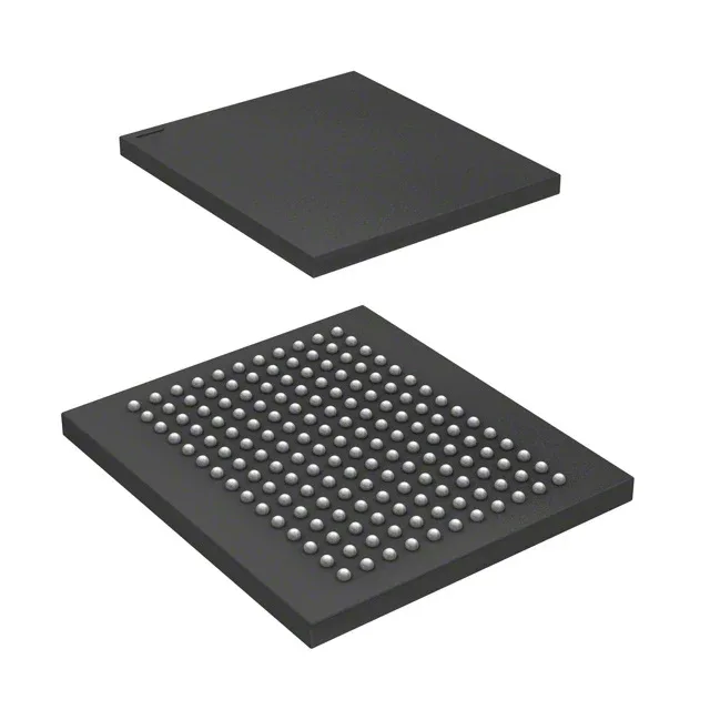
144 Mbit QDR II SRAM at 360 MHz — what this part is
It clocks at 360 MHz on the parallel interface, which means the memory can deliver back-to-back read and write transactions on alternating clock edges without dead cycles — the defining advantage of the QDR II family over standard synchronous SRAM.
At 360 MHz the QDR II interface transfers data on both rising and falling edges of the clock, effectively doubling the data rate relative to the clock frequency. For a x18-wide bus that works out to a peak bandwidth of roughly 12.96 Gbit/s (360 MHz x 2 edges x 18 bits). The practical throughput depends on your controller's ability to keep the pipeline full — the QDR II protocol eliminates the turnaround cycles that plague shared-bus SRAM, so back-to-back reads and writes sustain near the theoretical limit. The price of that throughput is tight timing closure on the PCB: the 360 MHz clock demands controlled-impedance traces, matched lengths, and clean supply decoupling right at the FBGA balls.
Storage temperature exceeds operating range — handling, not running, is what that limit governs.
Package and mounting — 165-ball FBGA
The package is a 165-ball fine-pitch ball grid array (FBGA) measuring 15x17 mm. The balls are on a standard pitch.
The base product number is CY7C1612, so any PCN or EOL notification for the family will carry that prefix.