200 MHz synchronous burst and 3 ns access — what they mean for the bus
The CY7C1386D-200AXCT: The 200 MHz clock rate sets the maximum synchronous operating frequency for the SDR (single-data-rate) interface. At this clock, the 3 ns access time is the delay from the clock edge to valid data on the output pins — the bus timing budget must accommodate this plus the PCB trace flight time and the receiver setup/hold window. The 512K x 36 organization (18 Mbit total) provides a 36-bit wide word per address. This width suits applications that move wide data words per cycle — DSP coefficient tables, packet buffer descriptors, or cache tag stores — without needing to concatenate multiple narrower memory chips.
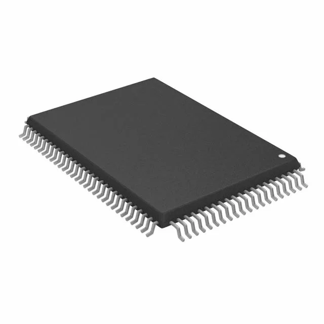
Both the core logic and the I/O buffers share this single supply; no separate VDDQ rail is needed. The 100-LQFP package (also designated 100-TQFP, 14x20 mm body) has a 0.5 mm pitch.
Parallel interface and synchronous architecture
The memory interface is parallel — address and data share the same port, and all control signals (chip enable, output enable, write enable) are synchronous to the clock. This contrasts with serial SRAMs that trade throughput for pin count; the parallel bus delivers the full 200 MHz burst rate but requires more board traces. As a volatile SRAM, the CY7C1386D-200AXCT retains data only while power is applied. No refresh cycles are needed (unlike DRAM), but the contents are lost at power-down. The synchronous SDR architecture means the address is latched on the rising clock edge and the data is driven on the same edge — no asynchronous address transition detection.