Infineon lists the CY7C1362C-200AXCT as Obsolete. For production or repair BOM lines that already carry this order code, the only supply path is the independent surplus-and-broker channel. The Tape & Reel packaging is standard for volume pick-and-place assembly, so reel quantities are the norm for this part.
200 MHz clock, 3 ns access — timing fit for pipelined data paths
The CY7C1362C-200AXCT is a synchronous SDR (Single Data Rate) SRAM with a 200 MHz clock input and a 3 ns access time from clock edge. The 200 MHz clock rate means the part can sustain one read or write per cycle, delivering a 200 MT/s peak bandwidth on the 18-bit data bus. The 3 ns access time is the delay from the rising clock edge to valid data on the outputs; at 200 MHz the cycle period is 5 ns, so the 3 ns access consumes 60% of the cycle — the remaining 2 ns must cover the output hold and the receiver's setup time. This is typical for synchronous SRAMs of this generation; the timing closure margin depends on the PCB trace delay and the load capacitance of the receiving device. Memory organization is 512K words by 18 bits, giving a total density of 9 Mbit. The 18-bit word width includes 16 data bits plus two parity or ECC bits if the system uses them, or the extra two bits can serve as byte-lane selects in a wider memory bus. The parallel interface uses address, data, and control signals on a shared bus — no serialisation overhead, but the board must route 18 data lines plus address and control traces to the device.
100-TQFP package and 3.135-3.6 V supply rail
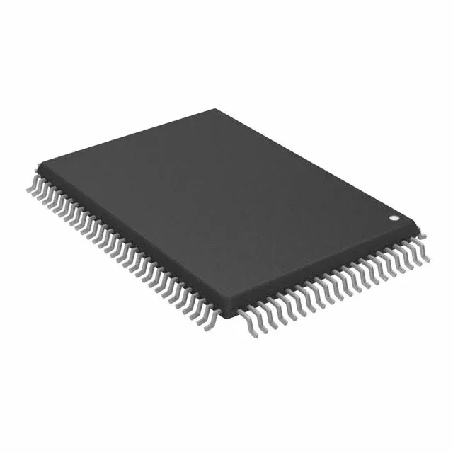
Housed in a 100-lead LQFP with the supplier package designation 100-TQFP (14x20 mm). The 0.5 mm pitch is typical for this pin count; the 14x20 mm body requires a 4-layer PCB for fan-out of the inner rows, though the outer rows can break out on a two-layer board if the trace density is low. The supply voltage range is 3.135 V to 3.6 V, which is a 3.3 V nominal rail with ±5% tolerance — a clean 3.3 V supply from a regulator or a POL converter is sufficient; no separate VDDQ or VTT rails are needed for this SDR interface. This limits the part to indoor, temperature-controlled environments — not suitable for extended outdoor, industrial, or automotive ambient without active cooling. The surface-mount package is standard for reflow assembly; the Tape & Reel format supports automated placement.