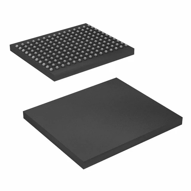
36 Mbit QDR II+ at 400 MHz — the timing budget driver
The CY7C1245KV18-400BZXI: This is the part that determines whether your memory controller can close timing on a high-throughput data path — the 400 MHz clock rate sets the read/write bandwidth ceiling, and the 1M x 36 organization feeds a 36-bit data bus without needing to bank-interleave. The QDR II+ architecture delivers separate read and write data ports, eliminating the bus-turnaround dead cycles that plague common-I/O SRAMs. At 400 MHz, the device can sustain a read and a write operation every clock cycle, giving a peak bandwidth of 3.6 GB/s on the 36-bit bus.
The 165-FBGA (13x15 mm) package has a 1.0 mm ball pitch, which requires a controlled impedance PCB stack-up and a via-in-pad design for the signal fan-out. The supply voltage tolerance of 1.7 V to 1.9 V means the core rail must stay within 100 mV of the nominal 1.8 V; a switching regulator with <1% load regulation is the usual choice. The 400 MHz clock input is a differential pair — the layout must match the trace lengths within 5 ps skew and keep the single-ended impedance at 50 Ω to ground. Decoupling should use a 0.1 µF and a 0.01 µF MLCC per supply pin, placed within 2 mm of the ball, plus a bulk 10 µF per quadrant of the package.
Availability and current pricing confirmed at RFQ time — no stock-holding claim, but the active status means lead times are typically quoted in weeks, not months.