Infineon Technologies CY7B991-5JCT — Clock & Timing ICs

Cypress CY7B991-5JCT RoboClock PLL Clock Driver, 80 MHz

MPNCY7B991-5JCT
End of Life

Cypress RoboClock CY7B991-5JCT, PLL-based fanout buffer / zero delay buffer, 80 MHz max, 1:8 CMOS I/O, 4.5-5.5 V supply, 32-PLCC (J-Lead), commercial temp.

$11.77Ref. price · indicative, final on quote
Packaging32-LCC (J-Lead)
StockContact for availability
MOQ1 pcs
  • 100% new & originalTraceable channels only — no refurbs, no pulls, no remarked parts.
  • Date & lot codes on quoteStated per line before you commit; label photos on request.
  • MSL-compliant ESD packingMoisture-sealed bags with indicator cards; reels photo-verified.
  • PayPal buyer protectionPay by T/T, PayPal or Payoneer — card payments covered end to end.

Specifications

CY7B991-5JCT Technical Specifications
ParameterValue
TypeFanout Buffer (Distribution), Zero Delay Buffer
SeriesRoboClock™
Mounting typeSurface Mount
Voltage4.5V ~ 5.5V
Frequency80MHz
Operating temperature0°C ~ 70°C (TA)
PLLYes
InputCMOS
OutputCMOS
PackageBulk
Case32-LCC (J-Lead)
Divider (Multiplier)Yes/No
Number of circuits1
Ratio - Input:Output1:8
Differential - Input:OutputNo/No

Product details

PLL-based clock fanout at 80 MHz — what it means for the bus

The Cypress CY7B991-5JCT is a PLL-based fanout buffer and zero delay buffer from the RoboClock series. It takes one CMOS input and distributes it to eight CMOS outputs at up to 80 MHz, with the internal PLL aligning the output edges to the input for zero propagation delay. This makes it a fit for clock distribution in synchronous digital systems where timing margin is tight — PCI bus, memory controllers, or networking gear that needs one clean clock tree without adding skew.

1:8 fanout and 80 MHz ceiling — sizing the clock tree

The 1:8 input-to-output ratio means a single CY7B991-5JCT can drive up to eight loads from one clock source, reducing the number of buffers on the board. The 80 MHz maximum frequency covers most standard logic and memory interfaces — SDRAM, 10/100 Ethernet MACs, and 8- or 16-bit microcontrollers — but falls short for gigabit-class serial links or DDR3/4 clocking. If your design runs above 80 MHz, you need a different part. Supply voltage is 4.5 V to 5.5 V, so this is a 5 V nominal part. It will not run from a 3.3 V rail without a regulator. The commercial temperature range (0°C to 70°C) limits it to indoor, office, or lab environments — not for outdoor telecom cabinets or under-hood automotive.

Package and footprint — 32-PLCC with J-leads

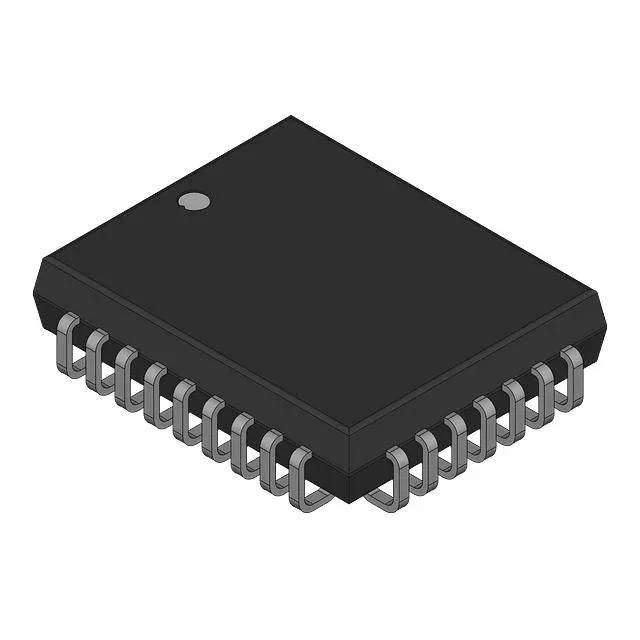
The CY7B991-5JCT comes in a 32-lead PLCC with J-leads (bent under the body). This is a surface-mount package that can also be socketed with a PLCC socket. The J-lead footprint is less common than gull-wing (SOIC, TSSOP) — verify your PCB land pattern matches the J-lead geometry. The supplier device package is 32-PLCC (11.43x13.97 mm).

Lifecycle and sourcing — active, no EOL watch needed

The CY7B991-5JCT is listed as Active on the lifecycle record. For a BOM line, this is a low-risk part to qualify — no last-time-buy scramble, no forced redesign. The part is RoHS non-compliant, so if your assembly line is RoHS-only, factor in a leaded-process exemption or look for a halogen-free alternate.

Frequently asked questions

What is the maximum frequency of CY7B991-5JCT?

The maximum frequency is 80 MHz. That covers most standard logic and memory interfaces but not gigabit serial links or high-speed DDR.