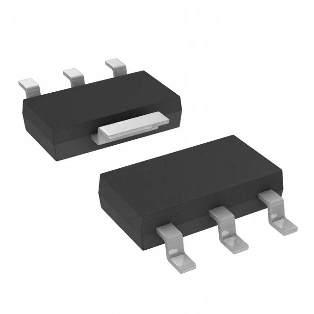
Infineon Technologies BTS3118NHUMA1 — Power Management (PMIC / Gate Driver)

Infineon BTS3118NHUMA1 HITFET Low-Side Switch, 70 mOhm

MPNBTS3118NHUMA1
Active

Infineon HITFET BTS3118NHUMA1, low-side N-channel switch, 70 mOhm typ Rds(on), 42 V max load, 2.17 A output, -40°C to 150°C, PG-SOT223-4, active.

$2.1000Ref. price · indicative, final on quote
Independent supplier — new & surplus stockAuthenticity-screened · ESD-safe packingListing updated Jul 2026

Specifications

BTS3118NHUMA1 specifications
ParameterValue
SeriesHITFET®
Input typeNon-Inverting
Output typeN-Channel
TypeGeneral Purpose
MountingSurface Mount
Voltage - load42V (Max)
Voltage - supply (Vcc (Vdd))Not Required
Output current2.17A
I/O channels1
InterfaceOn/Off
Operating temperature-40°C~150°C(TJ)
PackageTape & Reel (TR); Cut Tape (CT)
Rds on70mOhm
CaseTO-261-4, TO-261AA
Fault protectionCurrent Limiting (Fixed), Over Temperature, Over Voltage
Output configurationLow Side
Ratio - Input:Output1:1

Product details

It is a current-production Infineon HITFET device, not an NRND or EOL part that forces a redesign cycle.

70 mOhm Rds(on) — the conduction loss floor

The typical on-resistance is 70 mOhm. At the 2.17 A maximum continuous output, that works out to about 330 mW of conduction loss at 25°C junction. The PG-SOT223-4 package with its exposed tab can handle that without thermal runaway, but derate above 85°C ambient — the RthJA climbs and the 150°C junction limit comes into play.

42 V load rail — 24 V automotive with headroom

The load voltage is rated to 42 V maximum. That covers a 24 V nominal industrial bus with margin for transients, and it handles the 12 V automotive load-dump spike that can hit 35 V. The 2.17 A output ceiling suits solenoid, relay, lamp and small motor loads in those environments.

Built-in fault protection — no external clamp needed

The BTS3118NHUMA1 integrates current limiting (fixed), over-temperature shutdown, and over-voltage protection. That means you can drop this switch into a 24 V or 12 V load circuit without adding a series resistor for inrush or a TVS for inductive kickback — the device handles it internally. The non-inverting input and 1:1 ratio make it a straight drop-in for a logic-level gate signal.

PG-SOT223-4 footprint — board layout note

The package is PG-SOT223-4 (TO-261-4 equivalent). The exposed tab on the bottom is the drain connection and the primary thermal path. On a 2-layer board, a copper pour under the tab with vias to the ground plane keeps the junction temperature below 125°C at full load. The surface-mount assembly is standard reflow — no special profile needed.

Frequently asked questions

What is the typical Rds(on) of the BTS3118NHUMA1?

The typical on-resistance is 70 mOhm. This is the conduction loss floor at 25°C junction; expect it to increase by roughly 50% at 150°C junction per the normalised curve in the datasheet.

Does the BTS3118NHUMA1 have over-temperature protection?

Yes, it integrates over-temperature shutdown along with fixed current limiting and over-voltage protection. No external protection components are required for typical inductive or resistive loads within the 42 V / 2.17 A envelope.

Is the BTS3118NHUMA1 a low-side or high-side switch?

It is a low-side N-channel switch. The output is N-channel, the load connects between the supply rail and the drain, and the source is grounded through the PG-SOT223-4 tab.