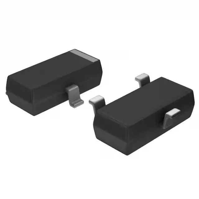
RF front-end transistor for 900 MHz to 1.8 GHz bands
The BFR193E6327HTSA1 is an NPN silicon RF transistor from Infineon designed for low-noise amplifier and driver stages up to 8 GHz. With a transition frequency of 8 GHz and a noise figure of 1 dB to 1.6 dB across the 900 MHz to 1.8 GHz cellular and ISM bands, this part suits receiver front-ends where sensitivity matters — the noise figure directly sets the cascaded system NF, so a 1 dB floor here keeps the LNA from dominating the receive chain budget. Gain spans 10 dB to 15 dB depending on bias and frequency — enough for a single-stage LNA or buffer before the mixer. The 80 mA maximum collector current and 12 V Vceo breakdown mean it handles moderate power levels in driver or oscillator buffer stages without thermal stress in the SOT-23-3 package.
Gain, noise figure, and bias point selection
The 10 dB to 15 dB gain range is specified without a fixed bias condition — the designer dials in the collector current via the emitter resistor to hit the target gain and noise figure simultaneously. At 30 mA and 8 V, the minimum DC current gain (hFE) is 70, which gives enough loop gain for the bias network to stay stable over temperature. Noise figure is 1 dB typical at 900 MHz, rising to 1.6 dB at 1.8 GHz — the increase tracks the device's fT margin. For a 1.8 GHz LNA, the input match should be tuned for minimum NF rather than maximum gain; the 8 GHz fT provides enough headroom that the trade-off is manageable without external degeneration. Maximum power dissipation is 580 mW at the SOT-23-3 junction — this is the thermal ceiling for continuous operation. In a 50-ohm system with 12 V supply, the transistor dissipates roughly Vce × Ic; staying under 300 mW keeps the junction below 150°C with standard FR4 copper land patterns.
The BFR193E6327HTSA1 comes in the industry-standard SOT-23-3 package (also designated PG-SOT23 by Infineon). The three-pin layout — base, emitter, collector — matches the common RF transistor footprint used across the BFR/BFP series, so a single PCB land pattern serves multiple gain and noise figure variants. The tape-and-reel or cut-tape packaging options suit prototype builds and production volumes alike.
Active lifecycle and compliance status
ROHS3 compliant, with no restricted substances above the threshold limits. The operating junction temperature range extends to 150°C, covering industrial and telecom ambient conditions with margin.
Pin-to-pin alternative: BFP193E6327HTSA1
The BFP193E6327HTSA1 is a direct pin-to-pin alternative in the same SOT-23-3 footprint and package option. Its gain range is 12 dB to 18 dB — roughly 2-3 dB higher across the band — while the noise figure and transition frequency are identical. If the design needs more gain margin without a layout change, the BFP193 drops in with no board spin.