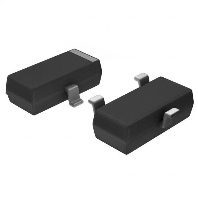
Infineon Technologies BFR106E6327HTSA1 — Discrete Semiconductors

BFR106E6327HTSA1 NPN RF Transistor, 15V 5GHz SOT-23-3

MPNBFR106E6327HTSA1
End of Life

Infineon Technologies BFR106E6327HTSA1 NPN RF transistor, 15V Vceo, 5GHz fT, 8.5dB ~ 13dB gain, 1.8dB ~ 3dB noise figure, 700mW, SOT-23-3.

$0.43Ref. price · indicative, final on quote
PackagingTO-236-3, SC-59, SOT-23-3
StockContact for availability
Lead time3-5 Days wk
MOQ1 pcs
  • 100% new & originalTraceable channels only — no refurbs, no pulls, no remarked parts.
  • Date & lot codes on quoteStated per line before you commit; label photos on request.
  • MSL-compliant ESD packingMoisture-sealed bags with indicator cards; reels photo-verified.
  • PayPal buyer protectionPay by T/T, PayPal or Payoneer — card payments covered end to end.

Specifications

BFR106E6327HTSA1 Technical Specifications
ParameterValue
Mounting typeSurface Mount
FET typeNPN
Voltage - collector emitter breakdown15V
Current - collector (Ic)210mA
DC current gain (hFE) (Min) @ ic, vce70 @ 70mA, 8V
Power - max700mW
Frequency5GHz
Operating temperature150°C (TJ)
Gain8.5dB ~ 13dB
PackageTape & Reel (TR); Cut Tape (CT)
CaseTO-236-3, SC-59, SOT-23-3
Noise figure (dB typ @ f)1.8dB ~ 3dB @ 900MHz ~ 1.8Ghz

Product details

RF amplifier stage fit — gain, noise, and bandwidth

The BFR106E6327HTSA1 is an NPN RF transistor in a SOT-23-3 package (PG-SOT23), designed for small-signal amplifier stages up to the low-GHz band. Its 5 GHz transition frequency (fT) means the usable gain extends past 2 GHz before roll-off becomes significant — enough for 900 MHz ISM-band, 1.8 GHz GSM, or 2.4 GHz WLAN LNA and driver stages. Gain spans 8.5 dB to 13 dB across the bias range, and the noise figure runs 1.8 dB to 3 dB at 900 MHz to 1.8 GHz. That NF floor is competitive for a general-purpose RF transistor — it keeps the receiver's cascaded noise figure low enough for most commercial radio front-ends without resorting to a dedicated low-noise SiGe part.

DC bias headroom and thermal budget

Collector-emitter breakdown is 15 V, and maximum continuous collector current is 210 mA — enough headroom for a typical LNA biased at 5–8 V and 10–50 mA, with margin for supply ripple or transient overshoot. Power dissipation is rated at 700 mW maximum. In a SOT-23-3 on a standard FR4 board with minimal copper, the junction-to-ambient thermal resistance is typically 250–300 °C/W — at 700 mW the junction would hit 175–210 °C above ambient, exceeding the 150 °C TJ max. Real designs should derate to 300–400 mW for reliable operation in a 25 °C ambient, or use larger copper pads to spread heat.

Frequently asked questions

What is the gain of the BFR106E6327HTSA1?

The gain is listed as 8.5 dB to 13 dB, depending on bias conditions and frequency. The exact value within that range depends on the collector current and the impedance match at the operating frequency.