What this PNP pre-biased transistor does in the circuit
It integrates two 10 kOhm resistors — one in series with the base (R1) and one from base to emitter (R2) — so you can drive it directly from a logic output or microcontroller GPIO without external bias components. Collector current is rated to 500 mA, collector-emitter breakdown at 50 V, and the transition frequency hits 150 MHz, making it suitable for low-side load switching, relay and solenoid drivers, and inverter stages where you need to sink current from a positive rail.
Infineon lists the BCR583E6327HTSA1 as Not Recommended for New Design (NRND). For current BOM lines, plan a last-time-buy window or identify an alternate source before the NRND status escalates to end-of-life.
SOT-23 footprint — will it sit flat on the pad
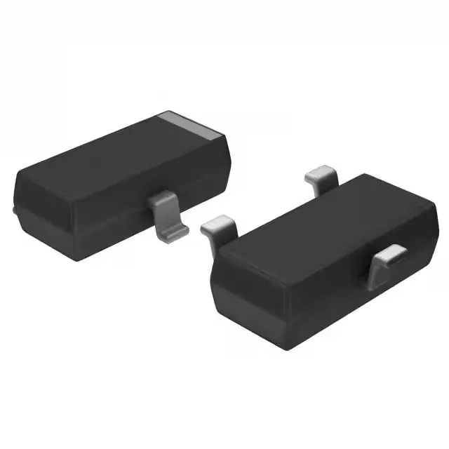
The part ships in a TO-236-3 / SC-59 / SOT-23-3 outline, which is the industry-standard three-lead small-signal transistor footprint. The supplier device package is PG-SOT23 (Infineon's designation). No exotic pad geometry — it places cleanly with standard SOT-23 land patterns.
Power dissipation and thermal reality
Maximum power dissipation is 330 mW. In a SOT-23 package without a heatsink, that limits continuous collector current well below the 500 mA peak — at 50 V Vce, the safe operating area is constrained by the package's thermal impedance. For pulsed or low-duty-cycle switching (e.g., driving a relay coil or small solenoid), the 500 mA rating is usable; for continuous DC load, derate aggressively or move to a larger package.