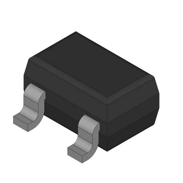
Pre-biased PNP in a SOT-323 footprint — AEC-Q101 for automotive and industrial
It integrates a 10 kΩ base resistor (R1) and a 47 kΩ emitter-base resistor (R2), eliminating two external passives per transistor and simplifying PCB layout in high-density modules. The 200 MHz transition frequency supports switching in gate drive, level shifting, and signal conditioning circuits up to the low-MHz range.
Built-in resistors — what they save on the BOM
The integrated 10 kΩ base resistor and 47 kΩ emitter-base resistor mean this single SOT-323 component replaces a discrete PNP transistor plus two chip resistors. For a 100-piece BOM line, that is 200 fewer passives to source, place, and inspect. The resistor ratio sets a fixed base current division, so the saturation voltage is predictable: 300 mV maximum at 500 µA base drive and 10 mA collector current. The DC current gain is a minimum of 70 at 5 mA collector current and 5 V VCE.
Automotive-grade screening — what AEC-Q101 means for reliability
It is rated for the automotive temperature range typical of under-hood and cabin electronics.
Package and footprint — SOT-323 layout notes
The BCR185WH6327 is supplied in the PG-SOT323-3-1 package (SC-70 equivalent), a 3-pin surface-mount package with a 1.3 mm body width and 0.65 mm lead pitch. The collector is the center pin; the base and emitter are on the outer pins. Maximum power dissipation is 250 mW, so thermal design should account for ambient temperature and board copper area.