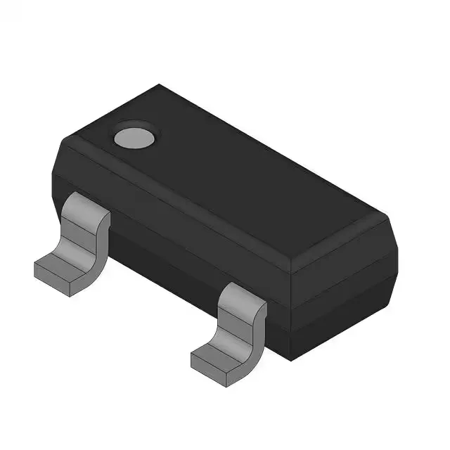
PNP pre-biased transistor with integrated resistors
This is a SOT-23-3 surface-mount device rated for 200 mW power dissipation and 100 mA collector current, with a 50 V collector-emitter breakdown voltage and a 200 MHz transition frequency.
R1 and R2 values — no external biasing needed
The BCR185E6327 integrates a 10 kΩ base resistor (R1) and a 47 kΩ emitter-base resistor (R2). These values set the turn-on threshold and base current limit, so the transistor switches on when the input voltage exceeds roughly 2.5 V at the base pin. For a 5 V logic drive, the base current is limited to about 250 µA, which is well within the 100 mA collector current rating. The 47 kΩ resistor across the base-emitter junction also provides a guaranteed off-state with the input pulled low, reducing leakage to the 100 nA ICBO maximum.
The BCR185E6327 is listed with an Automotive, AEC-Q101 qualification. For a buyer sourcing for an ECU, sensor module, or motor drive, this qualification eliminates the need for additional screening.
SOT-23-3 package — rework and layout notes
The BCR185E6327 comes in a PG-SOT23-3-1 package (SOT-23-3 footprint). The small thermal mass means it reflows cleanly with standard lead-free profiles; a hot-air station at 300 °C for a few seconds lifts the part without damaging the board pad. The package has no exposed pad, so the 200 mW power limit is the junction-to-ambient ceiling — keep the copper pour on the collector trace generous if running near the limit.