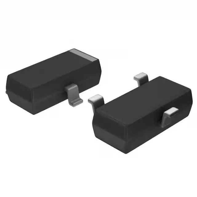
Pre-biased PNP — what the 10 kOhm resistors mean for the BOM
The built-in 10 kOhm base resistor (R1) and 10 kOhm emitter-base resistor (R2) eliminate two external passives from the board, shrinking the footprint for a common switching function — a logic-level output driving a relay coil, a small solenoid, or an LED string where the collector handles up to 100 mA and the Vce breakdown holds off 50 V. The 200 MHz transition frequency is fast enough for most low-frequency load switching but not a concern for high-side PWM above a few hundred kilohertz.
The base product number BCR183 covers the family; a pin-compatible sibling with the same 10 kOhm bias network and SOT-23 footprint is the likely drop-in path, but no official successor is listed on this record.
Vce saturation is specified at 300 mV maximum with 500 µA base drive and 10 mA collector current — a clean low-side switch for logic-level loads. The minimum DC current gain of 30 at 5 mA Ic and 5 Vce is typical for a pre-biased PNP; the built-in resistors set the base current, so the designer does not calculate an external base resistor, but the trade-off is that the saturation voltage and drive strength are fixed by the resistor ratio. The 100 nA maximum collector cutoff current (ICBO) is tight enough for battery-powered circuits where off-state leakage matters.