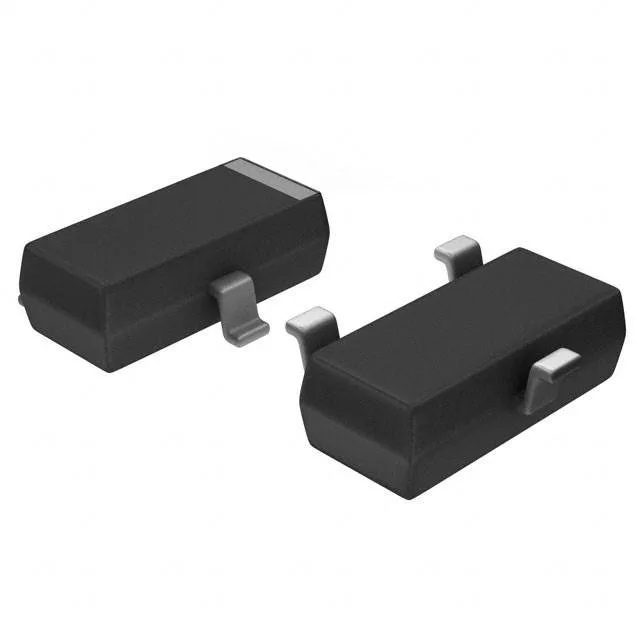
Infineon Technologies BCR108E6327HTSA1 — Discrete Semiconductors

BCR108E6327HTSA1 NPN Pre-Biased Transistor, 50 V, 100 mA

MPNBCR108E6327HTSA1
Last Buy

Infineon BCR108E6327HTSA1 NPN pre-biased transistor, 50 V Vce, 100 mA Ic, 170 MHz ft, R1 2.2 kOhm, R2 47 kOhm, PG-SOT23 package, 200 mW power dissipation.

$0.3600Ref. price · indicative, final on quote
StockContact for availability
MOQ1 pcs
  • 100% new & originalTraceable channels only — no refurbs, no pulls, no remarked parts.
  • Date & lot codes on quoteStated per line before you commit; label photos on request.
  • MSL-compliant ESD packingMoisture-sealed bags with indicator cards; reels photo-verified.
  • PayPal buyer protectionPay by T/T, PayPal or Payoneer — card payments covered end to end.

Specifications

BCR108E6327HTSA1 Technical Specifications
ParameterValue
Mounting typeSurface Mount
FET typeNPN - Pre-Biased
Voltage - collector emitter breakdown50 V
Current - collector (Ic)100 mA
Current - collector cutoff100nA (ICBO)
DC current gain (hFE) (Min) @ ic, vce70 @ 5mA, 5V
Power - max200 mW
Frequency170 MHz
PackageTape & Reel (TR) Cut Tape (CT)
CaseTO-236-3, SC-59, SOT-23-3
Resistor - base (R1)2.2 kOhms
Resistor - emitter base (R2)47 kOhms
Vce saturation (Max) @ ib, ic300mV @ 500µA, 10mA

Product details

Pre-biased NPN in a SOT-23 footprint

The Infineon BCR108E6327HTSA1 is an NPN pre-biased transistor that integrates two bias resistors — a 2.2 kOhm base resistor (R1) and a 47 kOhm emitter-base resistor (R2) — into a single PG-SOT23 package. This eliminates two discrete passives from the BOM and shrinks the placement area for switching and driver circuits where the base bias network is fixed. The device is rated for a 50 V collector-emitter breakdown and handles a continuous collector current of 100 mA, with a transition frequency of 170 MHz that suits moderate-speed switching up to the low-MHz range.

Last-time-buy — plan the BOM move now

The BCR108E6327HTSA1 carries a Last Buy lifecycle status. That means Infineon has issued a final purchase window, after which the part will no longer be manufactured. For any design still using this exact ordering code, procurement should secure the remaining lifetime volume or qualify a drop-in replacement before the LTB window closes.

R1 and R2 — the bias network is baked in

The integrated resistor divider sets the base drive relative to the collector load. With R1 at 2.2 kOhm and R2 at 47 kOhm, the transistor turns on when the input voltage exceeds roughly 0.7 V plus the divider ratio — a common configuration for low-side switches, relay drivers, and logic-level interface circuits where the base current is limited by the internal resistor. The 300 mV saturation voltage at 10 mA collector current (with 500 µA base drive) keeps conduction losses low in saturated switching.

Frequently asked questions

What are the specifications of BCR108E6327HTSA1 including R1 and R2 values?

It is rated for a 50 V collector-emitter breakdown, 100 mA continuous collector current, 170 MHz transition frequency, and a maximum power dissipation of 200 mW. The package is PG-SOT23 (SOT-23-3).