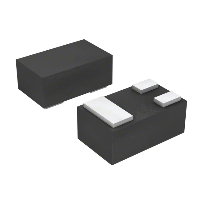
Infineon Technologies BCR 185L3 E6327 — Discrete Semiconductors

Infineon BCR 185L3 E6327 PNP Pre-Biased Transistor, 50 V

MPNBCR 185L3 E6327
End of Life

Infineon BCR 185L3 E6327 PNP pre-biased transistor, 50 V VCEO, 100 mA IC, 250 mW, 200 MHz fT, 10 kΩ base resistor, 47 kΩ base-emitter resistor, SOT-883/TSLP-3-4 package, tape and reel.

$0.4300Ref. price · indicative, final on quote
Independent supplier — new & surplus stockAuthenticity-screened · ESD-safe packingListing updated Aug 2026

Specifications

BCR 185L3 E6327 specifications
ParameterValue
MountingSurface Mount
FET typePNP - Pre-Biased
Voltage - collector emitter breakdown50 V
Current - collector (Ic)100 mA
Current - collector cutoff100nA (ICBO)
DC current gain (hFE) (Min) @ ic, vce70 @ 5mA, 5V
Power - max250 mW
Frequency - transition200 MHz
PackageTape & Reel (TR)
CaseSC-101, SOT-883
Resistor - base (R1)10 kOhms
Resistor - emitter base (R2)47 kOhms
Vce saturation (Max) @ ib, ic300mV @ 500µA, 10mA

Product details

Pre-biased PNP in a 0.6 x 1.0 mm footprint

The BCR 185L3 E6327: PNP pre-biased digital transistor with a 10 kΩ base resistor (R1) and a 47 kΩ base-emitter resistor (R2) in a SOT-883 package.

50 V / 100 mA — the practical switching envelope

Collector-emitter breakdown rated at 50 V, continuous collector current at 100 mA. Power dissipation limit is 250 mW.

200 MHz fT — fast enough for logic-level toggling

Transition frequency is 200 MHz, which supports switching up into the low-MHz range without significant gain roll-off. The minimum DC current gain is 70 at 5 mA, 5 V, so the part provides consistent drive across the operating region. The 100 nA maximum collector cutoff current keeps leakage negligible in battery circuits.

Frequently asked questions

What is the equivalent of BCR 185L3 E6327?

Within the BCR 185 family, the key parametric difference between variants is the built-in resistor ratio. The BCR 185L3 uses a 10 kΩ base resistor and 47 kΩ base-emitter resistor. A sibling with different resistor values (e.g., 2.2 kΩ / 47 kΩ or 10 kΩ / 10 kΩ) would change the on-threshold and saturation drive, so verify the resistor divider against your base-drive requirement before substituting.