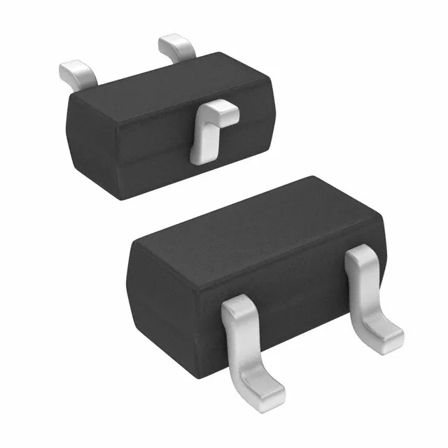
Infineon Technologies BCR 101T E6327 — Discrete Semiconductors

Infineon BCR 101T E6327 NPN Pre-Biased Transistor, 50 V

MPNBCR 101T E6327
End of Life

Infineon BCR 101T E6327 NPN pre-biased transistor, 50 V Vce, 50 mA Ic, 100 MHz fT, 250 mW, SC-75 SOT-416 package, surface mount.

StockContact for availability
MOQ1 pcs
  • 100% new & originalTraceable channels only — no refurbs, no pulls, no remarked parts.
  • Date & lot codes on quoteStated per line before you commit; label photos on request.
  • MSL-compliant ESD packingMoisture-sealed bags with indicator cards; reels photo-verified.
  • PayPal buyer protectionPay by T/T, PayPal or Payoneer — card payments covered end to end.

Specifications

BCR 101T E6327 Technical Specifications
ParameterValue
Mounting typeSurface Mount
FET typeNPN - Pre-Biased
Voltage - collector emitter breakdown50 V
Current - collector (Ic)50 mA
Current - collector cutoff100nA (ICBO)
DC current gain (hFE) (Min) @ ic, vce70 @ 5mA, 5V
Power - max250 mW
Frequency100 MHz
PackageTape & Reel (TR)
CaseSC-75, SOT-416
Resistor - base (R1)100 kOhms
Resistor - emitter base (R2)100 kOhms
Vce saturation (Max) @ ib, ic300mV @ 250µA, 5mA

Product details

Pre-biased NPN — what the integrated resistors save you

The BCR 101T E6327 is a pre-biased NPN transistor from Infineon with two 100 kΩ resistors integrated between base and emitter (R1 and R2). This means the base bias network is already on-die — you drop two external resistors from the BOM and shrink the placement footprint to a single SC-75 package. The transistor itself is rated for a collector current of 50 mA and a collector-emitter breakdown voltage of 50 V, with a DC current gain (hFE) of 70 minimum at 5 mA, 5 V. Transition frequency is 100 MHz, so it handles low-speed switching and level-shifting in digital or analog interface circuits without issue.

Maximum power dissipation is 250 mW.

Frequently asked questions

Does BCR 101T E6327 have built-in resistors?

Yes, the BCR 101T E6327 is an NPN pre-biased transistor with two 100 kΩ resistors — one in series with the base (R1) and one between base and emitter (R2).