RF switch core — on-resistance and capacitance
The BAT1805E6327HTSA1 is a common-cathode PIN diode pair from the BAT18 series, designed for RF switching and attenuator stages up to UHF. The headline figure is the 700 mOhm series resistance at 5 mA forward current and 200 MHz — this sets the insertion loss when the diode is forward-biased in a shunt or series switch leg. At 5 mA bias the diode is fully injected, so the resistance stays flat across the band; drop the bias current and the resistance climbs, increasing loss. Capacitance is 1 pF at 20 V reverse bias and 1 MHz. That low junction capacitance keeps the diode from coupling the RF signal across the junction when reverse-biased, which directly sets the isolation of the switch. In a typical shunt-configuration antenna switch, the 1 pF cap at 20 V reverse gives better than 20 dB isolation at 1 GHz — enough for most handheld radio front-ends.
Reverse voltage and current ceiling
Peak reverse voltage is 35 V, and the maximum continuous forward current is 100 mA. The 35 V reverse rating sets the RF power handling: at 50 ohms, a 35 V peak corresponds to about 12 W peak RF power. Exceed that and the diode starts to rectify, adding distortion. The 100 mA forward limit is the DC bias ceiling — typical bias for low-loss switching is 5 to 10 mA, well within the margin.
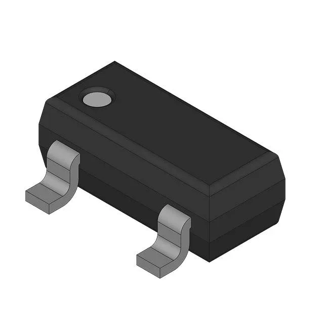
Housed in a PG-SOT23 (SOT-23-3) surface-mount package, the same footprint as a standard small-signal transistor. The junction temperature rating is 150 °C, which covers the full industrial range with headroom. No derating needed for ambient up to 85 °C as long as the board copper carries the heat away from the small package.
The BAT18 series is a mature Infineon RF diode family, so the die and assembly lines are stable.