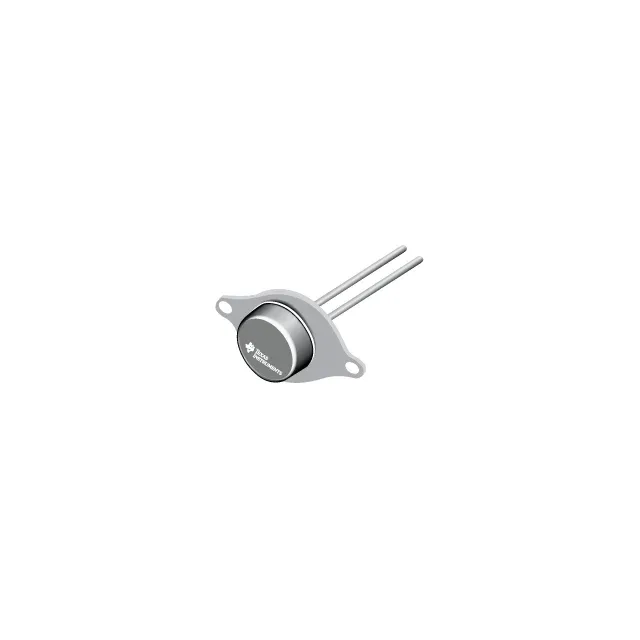
The 1 Ohm series resistance at 5 mA is the spec that decides insertion loss in a series switch or shunt attenuator — lower resistance means less signal power lost as heat. At 100 MHz, this value is already stable; the diode's PIN structure maintains low resistance well into the low-GHz range. The 0.9 pF capacitance at 3 V reverse bias sets the off-state isolation. In a shunt configuration, this capacitance couples the RF signal to ground; lower capacitance improves isolation at higher frequencies. For designs where the reverse voltage is lower than 3 V, expect slightly higher capacitance — factor that into your isolation budget. The 100 mW power dissipation and 100 mA max current limit the continuous RF power the diode can handle. The junction temperature rating of 150°C is the thermal constraint.
For BOM-line sourcing, this part does not carry the obsolescence risk that drives last-time-buy scrambles.