1 mOhm Rds(on) at 100 A — the conduction-loss ceiling
315 nC gate charge — sizing the driver stage
175 °C junction — thermal headroom for harsh environments
The 175 °C upper limit is rated for a 40 V FET. Power dissipation is 294 W at case temperature.
Package and procurement — PG-TO263-7-900 on Tape & Reel
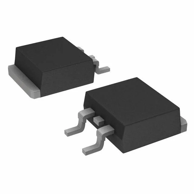
The AUIRFS8408-7TRL ships in the PG-TO263-7-900 package — a 7-lead D2PAK variant with an exposed drain tab. ROHS3 compliance is confirmed on the lifecycle record.
Date-code traceability and authenticity check
For a high-current part like this, the laser etch on the PG-TO263-7-900 body should show a consistent date-code font matching Infineon's plant marking for that week. The exposed drain tab should have a uniform solderable finish — any re-sanding or re-marking on the tab face is a red flag. Tape & Reel lots from independent distribution must show continuous date-code ranges; a single reel with mixed codes from different months warrants decap X-ray to verify the die matches the HEXFET® cell structure.