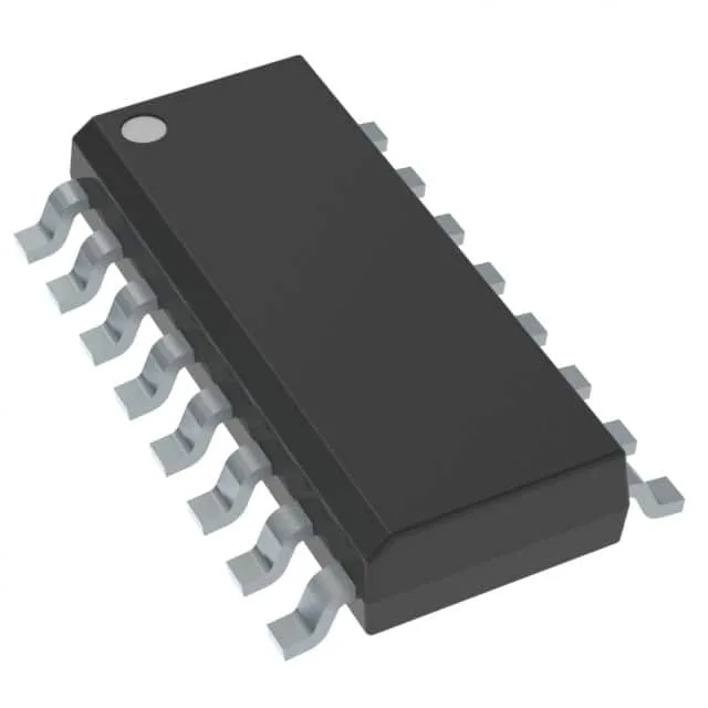
Infineon Technologies 2EDF9275FXUMA1

Infineon 2EDF9275FXUMA1 EiceDriver

MPN2EDF9275FXUMA1
End of Life

Infineon EiceDriver™ 2EDF9275FXUMA1, half-bridge gate driver, 2 independent channels, 4A source / 8A sink peak output, 20V supply, 650V bootstrap, 6.5ns rise / 4.5ns fall, -40°C to 125°C, 16-SOIC (PG-DSO-16-11).

$3.34Ref. price · indicative, final on quote
Packaging16-SOIC (0.154", 3.90mm Width)
StockContact for availability
MOQ1 pcs
  • 100% new & originalTraceable channels only — no refurbs, no pulls, no remarked parts.
  • Date & lot codes on quoteStated per line before you commit; label photos on request.
  • MSL-compliant ESD packingMoisture-sealed bags with indicator cards; reels photo-verified.
  • PayPal buyer protectionPay by T/T, PayPal or Payoneer — card payments covered end to end.

Specifications

2EDF9275FXUMA1 Technical Specifications
ParameterValue
SeriesEiceDriver™
Gate typeIGBT, SiC MOSFET
Input typeNon-Inverting
Channel typeIndependent
Mounting typeSurface Mount
Voltage20V
Logic voltage - VIL, VIH-, 1.65V
High side voltage - max (Bootstrap)650 V
Current - peak output (Source, sink)4A, 8A
Operating temperature-40°C ~ 125°C (TA)
PackageTape & Reel (TR); Cut Tape (CT)
Case16-SOIC (0.154\", 3.90mm Width)
Number of drivers2
Driven configurationHalf-Bridge
Rise (Fall time)6.5ns, 4.5ns

Product details

Infineon lists the 2EDF9275FXUMA1 as Active.

4 A source, 8 A sink — asymmetric drive for fast turn-off

The 2EDF9275FXUMA1 delivers 4 A peak source and 8 A peak sink. The 2:1 sink-to-source ratio is deliberate: it pulls the gate down harder than it pushes up, which shortens the turn-off delay and reduces the dead-time window needed to prevent shoot-through. In a hard-switched half-bridge, that extra sink current buys margin against cross-conduction at high dV/dt. Rise and fall times are 6.5 ns and 4.5 ns typical. Those sub-10 ns edges mean the gate loop inductance — PCB trace from driver output to MOSFET/IGBT gate — must be kept under 10 nH to avoid ringing that exceeds the gate oxide rating. A tight layout with the driver placed within 10 mm of the power device is the norm.

650 V bootstrap — fits 400 VAC / 600 VDC rails

The high-side bootstrap pin is rated to 650 V maximum. That covers the DC bus of a three-phase motor drive with margin for switching overshoot.

1.65 V VIH — direct 3.3 V logic interface

The input logic-high threshold is 1.65 V. A 3.3 V MCU or DSP output drives it directly — no external level shifter or resistor divider needed. The VIL threshold is not specified in the listing, but the 1.65 V VIH is low enough that 1.8 V logic may also work with sufficient noise margin; bench verification is advised for 1.8 V systems.

Drives IGBT and SiC MOSFET — two independent channels

The gate type covers both IGBT and SiC MOSFET. The two channels are independent and non-inverting, so each channel can be used for the high-side and low-side of a half-bridge. The 20 V supply rail is typical for IGBT gate drive.

16-SOIC (PG-DSO-16-11) — surface-mount, industrial temp

Packaged in a 16-SOIC with body width 3.90 mm, the Infineon PG-DSO-16-11 footprint. ROHS3 compliant.

Frequently asked questions

Can 2EDF9275FXUMA1 drive SiC MOSFETs?

Yes. The gate type is explicitly listed for both IGBT and SiC MOSFET. The 20 V supply rail covers the typical 15 V to 18 V SiC gate drive voltage. The 4 A source / 8 A sink peak current is sufficient to charge and discharge the gate capacitance of common SiC dies in the 30 mOhm to 80 mOhm range within tens of nanoseconds.

What is the maximum switching frequency for 2EDF9275FXUMA1?

The evidence does not list a maximum switching frequency. The 6.5 ns rise and 4.5 ns fall times imply the driver can support switching frequencies well above 100 kHz in a typical half-bridge, but the practical limit depends on the gate charge of the power device, the bootstrap capacitor recharge time, and the thermal dissipation in the driver. For a specific frequency target, model the gate drive losses with your MOSFET/IGBT's Qg.