Radio stack and throughput envelope
The ESP32-PICO-D4 integrates a dual-mode 2.4 GHz radio supporting 802.11b/g/n WiFi at PHY rates up to 150 Mbps and Bluetooth v4.2 + EDR with Class 1, 2, and 3 power levels. The -98.4 dBm receive sensitivity sets the noise floor for link budget calculations — in a typical indoor deployment with 2 dB antenna loss and 3 dB fade margin, the module maintains a usable signal at roughly 80–100 m line-of-sight. The 20.5 dBm output power sits at the upper end of the 2.4 GHz ISM band limit; the PA linearity margin should be checked against the target regulatory mask (FCC 15.247 / ETSI EN 300 328) during pre-certification.
Integrated flash and memory footprint
4 MB of embedded flash is stacked in the SiP package — this is the program store for the application image, OTA update staging, and persistent configuration. For a typical IoT sensor firmware with an RTOS kernel, WiFi stack, and MQTT client, the image lands around 400–600 KB, leaving roughly 3.4 MB for OTA delta storage and file-system wear-leveling. The flash is not externally accessible; the firmware update strategy must budget the full erase/write cycle count of the internal NAND (typically 100k cycles per sector).
Package, footprint, and reflow considerations
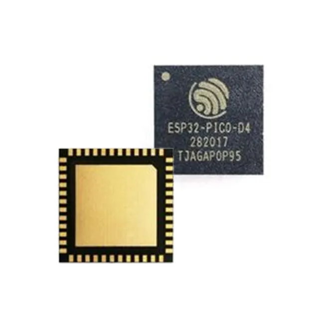
Housed in a 48-SMD Module with surface-mount termination, the ESP32-PICO-D4 presents a castellated edge-land pattern on a 0.80 mm pitch. The module contains the ESP32 die, crystal oscillator, flash, and passives in a single shielded package — the PCB footprint must clear the shield-can keep-out zone on the top layer and provide a solid ground plane beneath the module for thermal dissipation and RF return current. Reflow profile follows the JEDEC J-STD-020 standard for a moisture-sensitive component; the module's internal crystal and PA are sensitive to excessive peak temperature, so a ramp-soak-peak profile with a 245 °C peak and 30-second above 217 °C is recommended. The exposed centre pad (if present on the variant) should be stencilled with a single large aperture or an array of smaller apertures to avoid solder voiding under the RF die.
Operating temperature and deployment environment
This spans cold-chain storage, outdoor enclosure, and engine-adjacent installation where the internal die temperature may rise 15–20 °C above ambient under continuous WiFi transmission. The crystal oscillator's frequency drift over temperature is typically ±25 ppm; for applications requiring a precise beacon interval or time-synchronized mesh, a TCXO variant (ESP32-PICO-V3) should be considered.
Serial interface set and peripheral mapping
The module exposes GPIO, I²C, I²S, PWM, SDIO, SPI, and UART through its edge-land pads. The ESP32 core has three UARTs, two I²C controllers, four SPI buses, and 16 PWM channels — but the module's 48-pin footprint maps only a subset to external pins. Review the Espressif ESP32-PICO-D4 datasheet pin-assignment table (not reproduced here) to confirm which peripheral signals are bonded out; the SDIO interface, for example, shares pins with some GPIO lines and may require a pin-mux trade-off if both SD card and display are needed. The I²S bus supports up to 24-bit, 192 kHz audio; the PWM resolution is 16-bit at the base timer frequency.