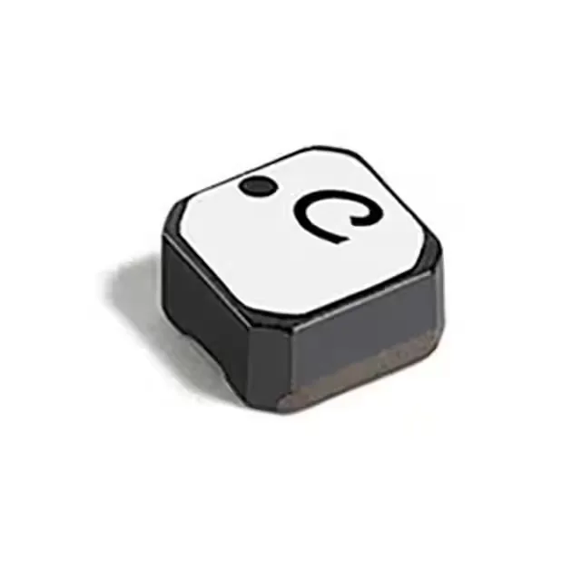
Inductance and current ratings for the power rail
The LPS3015-222MRC delivers 2.2 µH inductance at a 1.4 A continuous current rating, with a saturation current floor of 2.1 A — the saturation headroom means the inductor holds its value through transient peaks without abrupt roll-off. Maximum DC resistance is 110 mOhm, translating to roughly 0.22 W I²R loss at full rated current — a factor in thermal budgeting for a compact 2.95 mm × 2.95 mm footprint.
AEC-Q200 qualification and operating envelope
Rated AEC-Q200, the automotive-grade passive-component stress-qualification standard — this inductor passed the full suite of reliability tests (thermal shock, moisture resistance, mechanical shock, vibration) required for Tier-1 PPAP submission. Full operating temperature span is -40°C to +125°C, covering the under-hood ambient band with margin — the self-resonant frequency sits at 110 MHz, well above typical DC-DC converter switching frequencies, so the core material stays in its intended permeability range across the temperature range.
Shielding and board integration
Shielded construction contains the magnetic field within the ferrite core — critical when the inductor sits adjacent to sensitive analog or RF circuitry on the same PCB, as the stray field from an unshielded part couples into nearby traces. Surface-mount package (nonstandard 2.95 mm × 2.95 mm footprint), seated height 1.50 mm — the low profile fits under a 2 mm component clearance on a tightly stacked board.