It's a dedicated current-sense part — not a general-purpose op-amp pressed into service — so the input common-mode range and gain accuracy are optimised for shunt-resistor voltage drops. The 250 kHz -3 dB bandwidth and 0.9 V/µs slew rate are enough to capture load transients in motor-drive, solenoid, and power-supply feedback loops, while the 1 mA supply current keeps the quiescent burden low for always-on monitoring. Output is rail-to-rail, which maximises the usable signal swing into an ADC or comparator.
Supply range and why it narrows the BOM decision
The 4.5 V minimum supply span means this part will not run from a 3.3 V rail — it needs a 5 V bus or a regulated 5 V supply. That is a hard BOM constraint: if your board only has 3.3 V and 1.8 V, you add a 5 V rail or pick a different current-sense amplifier. The 5.5 V maximum also rules out direct connection to 12 V or 24 V industrial supplies without a local regulator. In practice, the MAX9919FASA+T fits best on a 5 V ±10% rail, which is common in automotive ECU power conditioning and industrial control modules.
Package and thermal relief
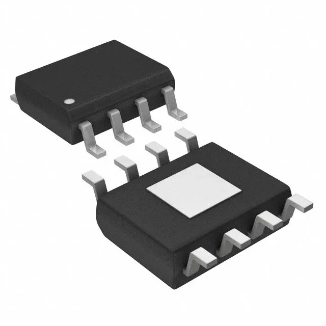
The 8-SOIC with exposed pad (8-SOIC-EP) is the key package detail for the rework bench. For continuous current-sense operation near the 125°C end of the range, that pad needs a solid copper pour and at least four vias to an inner ground plane. The surface-mount footprint is standard SOIC-8 wide-body, so no special stencil work.
For production planning, this part is still a safe design-in choice with no imminent obsolescence risk.