What this forward controller does on your board
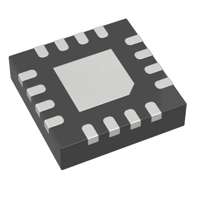
The MAX5974AETE+T is an offline forward-mode PWM switching controller from Analog Devices, designed for isolated power supplies up to 600 kHz switching frequency. It drives an external power switch (no internal FET) and includes control features like enable, frequency control, soft start, and synchronization. Fault protection covers current limiting, over-temperature, and short circuit — useful for keeping the downstream load safe during a fault event.
Key ratings and what they mean for your supply design
The 80% maximum duty cycle is typical for forward converters — it leaves the reset winding time to demagnetize the transformer core, preventing saturation. Switching frequency spans 100 kHz to 600 kHz, letting you trade off transformer size against switching losses: lower frequency shrinks core loss but needs a bigger magnetics, higher frequency shrinks the transformer but increases FET and rectifier losses. Startup voltage is 16 V, and the Vcc supply range is 7 V to 26 V — the controller wakes up once the auxiliary winding or bias rail crosses 16 V, then runs down to 7 V before undervoltage lockout kicks in. Output isolation is built into the control scheme, meaning the feedback loop crosses the isolation barrier — you still need an optocoupler or transformer-coupled feedback on the secondary side.